Asus P5G41-M LE/CSM User Manual
Asus P5G41-M LE/CSM Manual
 |
View all Asus P5G41-M LE/CSM manuals
Add to My Manuals
Save this manual to your list of manuals |
Asus P5G41-M LE/CSM manual content summary:
- Asus P5G41-M LE/CSM | User Manual - Page 1
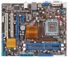
P5G41-M LE Motherboard - Asus P5G41-M LE/CSM | User Manual - Page 2
express written permission of ASUSTeK Computer Inc. ("ASUS"). Product warranty or service will not be extended if: (1) the ASUS HAS BEEN ADVISED OF THE POSSIBILITY OF SUCH DAMAGES ARISING FROM ANY DEFECT OR ERROR IN THIS MANUAL OR PRODUCT. SPECIFICATIONS AND INFORMATION CONTAINED IN THIS MANUAL - Asus P5G41-M LE/CSM | User Manual - Page 3
information vii About this guide viii P5G41-M LE specifications summary ix Chapter 1: Product introduction 1.1 Welcome 1-1 1.2 Package contents 1-1 1.3 Special features 1-1 1.3.1 Product highlights 1-1 1.3.2 Innovative ASUS features 1-2 1.4 Before you proceed 1-4 1.5 Motherboard overview - Asus P5G41-M LE/CSM | User Manual - Page 4
system 1-32 1.11.2 Support DVD information 1-32 Chapter 2: BIOS information 2.1 Managing and updating your BIOS 2-1 2.1.1 ASUS Update utility 2-1 2.1.2 ASUS EZ Flash 2 utility 2-2 2.1.3 ASUS CrashFree BIOS 3 utility 2-3 2.2 BIOS setup program 2-4 2.2.1 BIOS menu screen 2-5 2.2.2 Menu - Asus P5G41-M LE/CSM | User Manual - Page 5
Contents 2.5.4 Anti Surgy Support [Enabled 2-15 2.5.5 APM Configuration 2-15 2.5.6 Hardware Monitor 2-16 2.6 Boot menu 2-17 2.6.1 Boot Device Priority 2-17 2.6.2 Boot Settings Configuration 2-17 2.6.3 Security 2-18 2.7 Tools menu 2-19 2.7.1 ASUS EZ Flash 2 2-19 2.7.2 AI NET 2 2-19 2.8 Exit - Asus P5G41-M LE/CSM | User Manual - Page 6
in our products at ASUS REACH website at http://green.asus.com/english/REACH.htm. and used in accordance with manufacturer's instructions, may cause harmful interference to radio communications with Canadian ICES-003. DO NOT throw the motherboard in municipal waste. This product has been designed - Asus P5G41-M LE/CSM | User Manual - Page 7
motherboard service technician or your retailer. • The optical S/PDIF is an optional component (may or may not be included in your motherboard INSTRUCTIONS. Operation safety • Before installing the motherboard and adding devices on it, carefully read all the manuals wet. This motherboard should only be - Asus P5G41-M LE/CSM | User Manual - Page 8
need when installing and configuring the motherboard. How this guide is organized This guide contains the following parts: • Chapter 1: Product introduction This chapter describes the features of the motherboard and the new technology it supports. • Chapter 2: BIOS information This chapter tells how - Asus P5G41-M LE/CSM | User Manual - Page 9
P5G41-M LE specifications summary CPU Chipset Front Side Bus Memory Graphics Expansion Slots Storage LAN Audio USB ASUS Overclocking Features LGA775 socket for Intel® Core™2 Quad / Core™2 Extreme / Core™2 Duo / Pentium® dual-core / Celeron® dual-core / Celeron® processors Supports Intel® 45nm - Asus P5G41-M LE/CSM | User Manual - Page 10
BIOS v2.5 Support DVD Contents Drivers ASUS PC Probe II ASUS LiveUpdate Utility Anti-virus software (OEM version) Accessories 2 x Serial ATA cables 1 x Ultra DMA 100/66 cable 1 x I/O shield User Manual Form factor MicroATX form factor: 9.6 in x 7.8 in (24.4 cm x 19.8 cm) *Specifications are - Asus P5G41-M LE/CSM | User Manual - Page 11
the list below. 1.2 Package contents Check your motherboard package for the following items. Motherboard Cables Accessories Application DVD Documentation ASUS P5G41-M LE motherboard 2 x Serial ATA cables 1 x Ultra DMA 100/66 cable 1 x I/O shield ASUS motherboard support DVD User Manual If - Asus P5G41-M LE/CSM | User Manual - Page 12
of this motherboard supports dual VGA output of both DVI-D/HDMI and RGB. Innovative ASUS features ASUS MyLogo2™ This feature allows you to convert your favorite photo into a 256-color boot logo for a more colorful and vivid image on your screen. ASUS CrashFree BIOS 3 ASUS CrashFree BIOS 3 is an - Asus P5G41-M LE/CSM | User Manual - Page 13
and the BIOS automatically restores the CPU parameters to their default settings. Green ASUS This motherboard and its ASUS vision of creating environment-friendly and recyclable products/packaging to safeguard consumers' health while minimizing the impact on the environment. ASUS P5G41-M LE - Asus P5G41-M LE/CSM | User Manual - Page 14
that you must shut down the system and unplug the power cable before removing or plugging in any motherboard component. The illustration below shows the location of the onboard LED. SB_PWR P5G41-M LE ON OFF Standy Power Powered Off P5G41-M LE Onboard LED 1-4 Chapter 1: Product introduction - Asus P5G41-M LE/CSM | User Manual - Page 15
as indicated in the image below. 1.5.2 Screw holes Place six screws into the holes indicated by circles to secure the motherboard to the chassis. Do not overtighten the screws! Doing so can damage the motherboard. Place this side towards the rear of the chassis P5G41-M LE ASUS P5G41-M LE 1-5 - Asus P5G41-M LE/CSM | User Manual - Page 16
(64bit, 240-pin module) DDR2 DIMM_B1 (64bit, 240-pin module) PRI_IDE LGA775 7 VGA USB34 USBPW1-4 24.4cm(9.6in) LAN1_USB12 Atheros L1E Intel® G41 ICS 9LRS954 AUDIO 2 PCIEX1_1 Lithium Cell CMOS Power EATXPWR Super I/O PCIEX16 P5G41-M LE PCI1 RTL Audio codec SPEAKER SPDIF_OUT COM1 AAFP - Asus P5G41-M LE/CSM | User Manual - Page 17
of the PnP cap. The motherboard supports Intel® LGA775 processors with the Intel® Enhanced Intel SpeedStep® Technology (EIST) and Hyper-Threading Technology. 1.6.1 Installing the CPU To install a CPU: 1. Locate the CPU socket on the motherboard. P5G41-M LE P5G41-M LE CPU socket 775 Before installing - Asus P5G41-M LE/CSM | User Manual - Page 18
to the socket pins, do not remove the PnP cap unless you are installing a CPU. 3. Lift the load lever in the direction of the arrow to a 135º cap from the load plate window to remove (4B). Retention tab A B Load lever PnP cap Load plate 4B 4A 3 5. Position the CPU over the socket, ensuring that - Asus P5G41-M LE/CSM | User Manual - Page 19
6. Apply some Thermal Interface Material to the exposed area of the CPU that the heatsink will be in contact with, ensuring that it is spread in an even thin directly. 7. Close the load plate (A), then push the load lever (B) until it snaps into the A retention tab. B ASUS P5G41-M LE 1-9 - Asus P5G41-M LE/CSM | User Manual - Page 20
install the heatsink and fan assembly. Ensure that you have installed the motherboard to the chassis before you install the CPU fan and heatsink assembly. To install the CPU heatsink and fan: 1. Place the heatsink on top of the installed CPU, ensuring that the four fasteners match the holes on the - Asus P5G41-M LE/CSM | User Manual - Page 21
the CPU heatsink and fan: 1. Disconnect the CPU fan cable from the connector on the motherboard. 2. Rotate each fastener counterclockwise. 3. Pull up two fasteners at a time in a diagonal sequence to disengage the heatsink and fan assembly from the motherboard. A B A B B A B A ASUS P5G41-M LE - Asus P5G41-M LE/CSM | User Manual - Page 22
. 1.7 System memory 1.7.1 Overview The motherboard comes with two Double Data Rate 2 (DDR2) Dual Inline Memory Modules (DIMM) sockets. The figure illustrates the location of the DDR2 DIMM sockets: DIMM_A1 DIMM_B1 P5G41-M LE Channel Channel A Channel B P5G41-M LE 240-pin DDR2 DIMM sockets - Asus P5G41-M LE/CSM | User Manual - Page 23
® OS when you want to install 4GB or more memory on the motherboard. • This motherboard does not support DIMMs made up of 256 megabits (Mb) chips or less. • This motherboard supports up to 8GB on Windows® XP Professional x64 and Windows® Vista x64 editions. You may install a maximum of 4GB DIMMs - Asus P5G41-M LE/CSM | User Manual - Page 24
P5G41-M LE Motherboard Qualified Vendors Lists (QVL) DDR2-667 MHz capability Size 512MB 1GB 2GB 1GB 512MB 512MB 512MB 2GB 1GB 1GB 1GB AM4B5708MIJS7E0627B DS MID095D62864M8CEC DS Heat-Sink Package DS Heat-Sink Package DIMM support A* B G.SKILL F2-5400PHU2-2GBNT 5-5-5-15 G.SKILL DS D2 - Asus P5G41-M LE/CSM | User Manual - Page 25
51280-3SEA07100 • MS18T 51280-3 • U2S12D30YP-6E • • U2S24D30TP-6E • • DDR2 800 Qualified Vendors List Size Vendor 2GB (2 x 1GB) 512MB DDR2 800 4GB (2 x 2GB) 1GB 512MB 2GB 2GB 4GB (2 x 2GB) Package Heat-Sink Package DIMM support A* B* •• •• •• •• •• •• ASUS P5G41-M LE 1-15 - Asus P5G41-M LE/CSM | User Manual - Page 26
DDR2 800 Qualified Vendors List Size 1GB 1GB 1GB 2GB 4GB 1GB 1GB 2GB 1GB 2GB 1GB 2GB -Sink Package E5108AJBG-8E-E 0803A9082 E5108AJBG-8E-E Heat-Sink Package Heat-Sink Package DIMM support A* B Kingston kingston KHX6400D2LL/1G KVR800D2N5/1G N/A Kingston DS N/A kingston DS Kingston - Asus P5G41-M LE/CSM | User Manual - Page 27
DDR2 800 Qualified Vendors List Size Vendor Part No. CL Chip Brand SS/DS Chip No. 2GB OCZ OCZ2P8004GK 5 1GB OCZ OCZ2P800R22GK 4 51280-2.5P0716 U2S12D30TP-8E U2S24D30TP-8E Heat-Sink Package Heat-Sink Package Heat-Sink Package DIMM support A* B •• •• •• ASUS P5G41-M LE 1-17 - Asus P5G41-M LE/CSM | User Manual - Page 28
Chip Brand SS/DS Chip No. N/A DS Heat-Sink Package DIMM support A* B* •• N/A DS Qimonda DS Transcend DS Heat-Sink Package •• 800HY818T1G800C2F-2.5 • • TQ123YBF8 T0747 •• DDR2 1066 Qualified Vendors List Size Vendor Part No. 2GB (2 x 1GB) A-data 2048MB A-DATA (2 x 1024MB) 2GB - Asus P5G41-M LE/CSM | User Manual - Page 29
• A*: Supports one module inserted into either slot as the single-channel memory configuration. • B*: Supports one pair of modules inserted into both the blue slots as one pair of dual-channel memory configuration. Visit the ASUS website at www.asus.com for the latest QVL. ASUS P5G41-M LE - Asus P5G41-M LE/CSM | User Manual - Page 30
severe damage to both the motherboard and the components. To install a DIMM: 1. Press the retaining clips outward to unlock a DDR2 DIMM socket. 2. Align press the retaining clips outward to unlock the DIMM. 2 Support the DIMM lightly with your fingers when pressing the retaining clips - Asus P5G41-M LE/CSM | User Manual - Page 31
x1 slot This motherboard supports PCI Express x1 network cards, SCSI cards, and other cards that comply with the PCI Express specifications. 1.8.5 PCI Express x16 slot This motherboard supports a PCI Express x16 graphics card that complies with the PCI Express specifications. ASUS P5G41-M LE 1-21 - Asus P5G41-M LE/CSM | User Manual - Page 32
memory of date, time, and system setup parameters by erasing the CMOS RTC RAM data. The onboard button cell battery powers the RAM data in CMOS, which include system setup information such as system passwords. CLRTC 12 23 P5G41-M LE Normal (Default) P5G41-M LE boot process and enter BIOS setup - Asus P5G41-M LE/CSM | User Manual - Page 33
in the BIOS. KBPWR 12 23 +5V +5VSB (Default) P5G41-M LE P5G41-M LE Keyboard Power Setting CPU, DRAM in slow refresh, power supply in reduced power mode). USBPW1-4 12 23 +5V +5VSB (Default) USBPW5-8 P5G41-M LE 12 23 +5V +5VSB (Default) P5G41-M LE USB Device Wake Up ASUS P5G41-M LE - Asus P5G41-M LE/CSM | User Manual - Page 34
Video Graphics Adapter (VGA) port. This 15-pin port is for a VGA monitor or other VGA-compatible devices. 3. LAN (RJ-45) port. This port allows Gigabit connection to a Local Area Network (LAN) through a network connects the tape, CD, DVD player, or other audio sources. 5. Line Out port (lime). This - Asus P5G41-M LE/CSM | User Manual - Page 35
P5G41-M LE SATA connectors 2. Speaker connector (4-pin SPEAKER) This 4-pin connector is for the chassis-mounted system warning speaker. The speaker allows you to hear system beeps and warnings. SPEAKER +5V GND GND Speaker Out P5G41-M LE PIN 1 P5G41-M LE Speaker Out Connector ASUS P5G41-M LE - Asus P5G41-M LE/CSM | User Manual - Page 36
: blue, black, and gray. Connect the blue connector to the motherboard's IDE connector, then select one of the following modes to configure 100/66/33 IDE devices. PRI_IDE PIN1 P5G41-M LE NOTE:Orient the red markings on the IDE ribbon cable to PIN 1. P5G41-M LE IDE connector If any device jumper is - Asus P5G41-M LE/CSM | User Manual - Page 37
, the system will not boot. • We recommend that you use a PSU with a higher power output when configuring a system with more power-consuming devices or when you intend to install additional devices. The system may become unstable or may not boot up if the power is inadequate. ASUS P5G41-M LE 1-27 - Asus P5G41-M LE/CSM | User Manual - Page 38
Rotation +12V GND P5G41-M LE fan connectors Do not forget to connect the CPU fan cables to the fan connector. Insufficient air flow inside the system may damage the motherboard components. This is not a jumper! Do not place a jumper cap on the fan connector! 6. Front panel audio connector (10 - Asus P5G41-M LE/CSM | User Manual - Page 39
a slot opening at the back of the system chassis. These USB connectors comply with USB 2.0 specification that supports up to 480 Mbps connection speed. USB+5V USB_P8USB_P8+ GND NC USB+5V USB_P6USB_P6+ GND NC P5G41-M LE USB56 PIN 1 USB78 PIN 1 USB+5V USB_P7USB_P7+ GND USB+5V USB_P5USB_P5+ GND - Asus P5G41-M LE/CSM | User Manual - Page 40
supports several chassis-mounted functions. F_PANEL PWR LED PWR BTN HD_LED RESET P5G41-M LE GND PWR PLEDPLED+ Reset Ground IDE_LEDIDE_LED+ PIN 1 P5G41-M LE or puts the system in sleep or soft-off mode depending on the BIOS settings. Pressing the power switch for more than four seconds while the - Asus P5G41-M LE/CSM | User Manual - Page 41
. Serial port connector (10-1 pin COM) This connector is for a serial (COM) port. Connect the serial port module cable to this connector, then install the module to a slot opening at the back of the system chassis. COM1 PIN 1 P5G41-M LE P5G41-M LE Serial port (COM1) connector ASUS P5G41-M LE 1-31 - Asus P5G41-M LE/CSM | User Manual - Page 42
to avail all motherboard features. The contents of the Support DVD are subject to change at any time without notice. Visit the ASUS website at www.asus.com for updates. To run the Support DVD Place the Support DVD to the optical drive. The DVD automatically displays the Drivers menu if Autorun - Asus P5G41-M LE/CSM | User Manual - Page 43
and update the motherboard BIOS in Windows® environment. • ASUS Update requires an Internet connection either through a network or an Internet Service Provider (ISP). • This utility is available in the support DVD that comes with the motherboard package. Installing ASUS Update To install ASUS Update - Asus P5G41-M LE/CSM | User Manual - Page 44
instructions to complete the updating process. 2.1.2 ASUS EZ Flash 2 utility The ASUS EZ Flash 2 feature allows you to update the BIOS without using an OS‑based utility. Before you start using this utility, download the latest BIOS file from the ASUS website at www.asus.com. To update the BIOS - Asus P5G41-M LE/CSM | User Manual - Page 45
the BIOS to prevent system boot failure! 2.1.3 ASUS CrashFree BIOS 3 utility The ASUS CrashFree BIOS 3 is an auto recovery tool that allows you to restore the BIOS file when it fails or gets corrupted during the updating process. You can update a corrupted BIOS file using the motherboard support DVD - Asus P5G41-M LE/CSM | User Manual - Page 46
or reset the system while updating the BIOS! Doing so can cause system boot failure! The recovered BIOS may not be the latest BIOS version for this motherboard. Download the latest BIOS file from the ASUS website at www.asus.com. 2.2 BIOS setup program This motherboard supports a programmable Serial - Asus P5G41-M LE/CSM | User Manual - Page 47
match what you see on your screen. • Visit the ASUS website at www.asus.com to download the latest BIOS file for this motherboard. 2.2.1 BIOS menu screen Menu items Menu bar Main Advanced Power Configuration fields BIOS SETUP UTILITY Boot Tools Exit General help System Time [00:31:48] System - Asus P5G41-M LE/CSM | User Manual - Page 48
display a list of options. Refer to 2.2.7 Pop-up window. 2.2.7 Pop-up window Select a menu item then press to display a pop-up window with the . Main Advanced BIOS SETUP UTILITY Power Boot Tools Exit Suspend Mode ACPI Version Features ACPI APIC support APM Configuration Hardware - Asus P5G41-M LE/CSM | User Manual - Page 49
if you are specifically configuring a CD-ROM drive. Select ARMD (ATAPI Removable Media Device) if your device is either a ZIP, LS-120, or MO drive. Configuration options: [Not Installed] [Auto] [CDROM] [ARMD] This item does not appear when you select the SATA 1/2/3/4 devices. ASUS P5G41-M LE 2-7 - Asus P5G41-M LE/CSM | User Manual - Page 50
the data transfer from and to the device occurs multiple sectors at a time if the device supports multi-sector transfer feature. When set to [Disabled], the data transfer from and to the device devices. Configuration options: [0] [5] [10] [15] [20] [25] [30] [35] 2-8 Chapter 2: BIOS information - Asus P5G41-M LE/CSM | User Manual - Page 51
one of the preset overclocking configuration options: Manual - allows you to individually set overclocking parameters. Auto - loads the optimal settings for the system. Overclock Profile - loads overclocking profiles with optimal parameters for stability when overclocking. ASUS P5G41-M LE 2-9 - Asus P5G41-M LE/CSM | User Manual - Page 52
MANUAL]. CPU Frequency [xxx] Displays the frequency sent by the clock generator to the system bus and PCI bus. The value of this item is auto-detected by the BIOS. Use the and keys to adjust the CPU set the DDR2 operating frequency. FSB value is 1333, 1066, and 800. FSB 1333 1066 800 Auto - Asus P5G41-M LE/CSM | User Manual - Page 53
the No-Execution Page Protection Technology. Setting this item to [Disabled] forces the XD feature flag to always return to zero (0). Configuration options: [Disabled] [Enabled] ASUS P5G41-M LE 2-11 - Asus P5G41-M LE/CSM | User Manual - Page 54
CPU that supports the primary boot device. memory. Configuration options: [128MB] [256MB] [Maximum DVMT] The [Maximum DVMT] option only appears when installing 1GB DDR2 DIMMs into the DIMM sockets. Protect Audio Video Path Mode [Lite] This item is not user- configurable. 2-12 Chapter 2: BIOS - Asus P5G41-M LE/CSM | User Manual - Page 55
[HD Audio] Allows you to select the front panel support type. If High Definition Audio Front Panel used, set this item to [HD Audio] mode. Configuration options: [AC97] [HD Audio] 2.4.4 Onboard to disable or enable the USB functions. Configuration options: [Disabled] [Enabled] ASUS P5G41-M LE 2-13 - Asus P5G41-M LE/CSM | User Manual - Page 56
Support [Auto] Allows you to enable or disable support detected, the legacy USB support is disabled. Configuration options the maximum time that the BIOS waits for the USB storage device to devices, and setting the memory size block for legacy No] When set to [No], BIOS configures all the devices in the - Asus P5G41-M LE/CSM | User Manual - Page 57
display the configuration options. Main Advanced Power BIOS SETUP UTILITY Boot Tools Exit Suspend Mode ACPI 2.0 Support ACPI APIC Support Anti Surgy Support [Auto] [Disabled] [Enabled] [Enabled] power loss. Configuration options: [Power Off] [Power On] [Last State] ASUS P5G41-M LE 2-15 - Asus P5G41-M LE/CSM | User Manual - Page 58
monitor automatically detects and displays the motherboard and CPU temperatures. Select Ignored if you do not wish to display the detected temperatures. CPU Fan Speed [xxxxRPM] or [ automatically detects the voltage output through the onboard voltage regulators. 2-16 Chapter 2: BIOS information - Asus P5G41-M LE/CSM | User Manual - Page 59
sub-menu. Main Advanced Power BIOS SETUP UTILITY Boot Tools Exit Boot Settings Boot Device Priority Boot Settings Configuration Security Specifies the Boot Device Priority sequence. A virtual floppy to run Setup during POST. Configuration options: [Disabled] [Enabled] ASUS P5G41-M LE 2-17 - Asus P5G41-M LE/CSM | User Manual - Page 60
. To clear the supervisor password, select the Change Supervisor Password then press twice. The message Password uninstalled appears. If you forget your BIOS password, you can clear it by erasing the CMOS Real Time Clock (RTC) RAM. See section 1.9 Jumpers for information on how to erase - Asus P5G41-M LE/CSM | User Manual - Page 61
the sub-menu. Main Advanced Power BIOS SETUP UTILITY Boot Tools Exit ASUS EZ Flash 2 AI NET 2 Press ENTER to run the utility to select and update BIOS. This utility supports 1.FAT 12/16/32 (r/w) 2.NTFS -On Self‑Test (POST). Configuration options: [Disabled] [Enabled] ASUS P5G41-M LE 2-19 - Asus P5G41-M LE/CSM | User Manual - Page 62
Changes Load Setup Defaults BIOS SETUP UTILITY Boot Tools Exit ExEixtitsyssytsetmemsesteutpup on the Setup menus. When you select this option or if you press , a confirmation window appears. Select OK to load default values. Select Exit & Save Changes or make other changes before
-
 1
1 -
 2
2 -
 3
3 -
 4
4 -
 5
5 -
 6
6 -
 7
7 -
8
-
9
-
10
-
11
-
12
-
13
-
14
-
15
-
16
-
17
-
18
-
19
-
20
-
21
-
22
-
23
-
24
-
25
-
26
-
27
-
28
-
29
-
30
-
31
-
32
-
33
-
34
-
35
-
36
-
37
-
38
-
39
-
40
-
41
-
42
-
43
-
44
-
45
-
46
-
47
-
48
-
49
-
50
-
51
-
52
-
53
-
54
-
55
-
56
-
57
-
58
-
59
-
60
-
61
-
62
 |
 |

Motherboard
P5G41-M LE