Asus P5G41-M LE/CSM User Manual - Page 38
P5G41-M LE fan connectors - cpu support
 |
View all Asus P5G41-M LE/CSM manuals
Add to My Manuals
Save this manual to your list of manuals |
Page 38 highlights
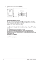
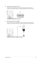
5. CPU and chassis fan connectors (4-pin CPU_FAN, 3-pin CHA_FAN) The fan connectors support cooling fans of 350 mA~2000 mA (24 W max.) or a total of 1 A~3.48 A (41.76 W max.) at +12V. Connect the fan cables to the fan connectors on the motherboard, ensuring that the black wire of each cable matches the ground pin of the connector. CPU_FAN GND CPU FAN PWR CPU FAN IN CPU FAN PWM P5G41-M LE CHA_FAN Rotation +12V GND P5G41-M LE fan connectors Do not forget to connect the CPU fan cables to the fan connector. Insufficient air flow inside the system may damage the motherboard components. This is not a jumper! Do not place a jumper cap on the fan connector! 6. Front panel audio connector (10-1 pin AAFP) This connector is for a chassis-mounted front panel audio I/O module that supports either HD Audio or legacy AC`97 audio standard. Connect one end of the front panel audio I/O module cable to this connector. GND PRESENCE# SENSE1_RETUR SENSE2_RETUR AGND NC NC NC AAFP PIN 1 PIN 1 MIC2 MICPWR Line out_R NC Line out_L PORT1 L PORT1 R PORT2 R SENSE_SEND PORT2 L P5G41-M LE HD-audio-compliant Legacy AC'97 pin definition compliant definition P5G41-M LE Analog front panel connector • We recommend that you connect a high-definition front panel audio module to this connector to avail of the motherboard's high-definition audio capability. • If you want to connect a high-definition front panel audio module to this connector, set the Front Panel Type item in the BIOS setup to [HD Audio]. If you want to connect an AC'97 front panel audio module to this connector, set the item to [AC97]. By default, this connector is set to [HD Audio]. See section 2.4.3 Chipset for details. 1-28 Chapter 1: Product introduction
-
 1
1 -
2
-
3
-
4
-
5
-
6
-
7
-
8
-
9
-
10
-
11
-
12
-
13
-
14
-
15
-
16
-
17
-
18
-
19
-
20
-
21
-
22
-
23
-
24
-
25
-
26
-
27
-
28
-
29
-
30
-
31
-
32
-
 33
33 -
 34
34 -
 35
35 -
 36
36 -
 37
37 -
 38
38 -
 39
39 -
 40
40 -
 41
41 -
 42
42 -
 43
43 -
44
-
45
-
46
-
47
-
48
-
49
-
50
-
51
-
52
-
53
-
54
-
55
-
56
-
57
-
58
-
59
-
60
-
61
-
62
 |
 |
