Asus P5G41T-M LX User Manual
Asus P5G41T-M LX Manual
 |
View all Asus P5G41T-M LX manuals
Add to My Manuals
Save this manual to your list of manuals |
Asus P5G41T-M LX manual content summary:
- Asus P5G41T-M LX | User Manual - Page 1
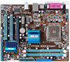
P5G41T-M LX Motherboard - Asus P5G41T-M LX | User Manual - Page 2
ASUS. ASUS ASSUMES NO RESPONSIBILITY OR LIABILITY FOR ANY ERRORS OR INACCURACIES THAT MAY APPEAR IN THIS MANUAL 2011, either (1) for free by downloading it from http://support.asus.com/download; or (2) for various Free Open Source Software licenses. If however you encounter any problems in obtaining - Asus P5G41T-M LX | User Manual - Page 3
information vii About this guide vii P5G41T-M LX specifications summary ix Chapter 1: Product introduction 1.1 Welcome 1-1 1.2 Package contents 1-1 1.3 Special features 1-1 1.3.1 Product highlights 1-1 1.3.2 Innovative ASUS features 1-2 1.4 Before you proceed 1-4 1.5 Motherboard overview - Asus P5G41T-M LX | User Manual - Page 4
BIOS 2-1 2.1.1 ASUS Update utility 2-1 2.1.2 ASUS EZ Flash 2 2-2 2.1.3 ASUS CrashFree BIOS 2-3 2.2 BIOS setup program 2-4 2.2.1 BIOS menu screen 2-5 2.2.2 Menu bar 2-5 2.2.3 Navigation keys 2-6 2.2.4 Menu items 2-6 2.2.5 Submenu items 2-6 2.2.6 Configuration fields 2-6 2.2.7 Pop-up window - Asus P5G41T-M LX | User Manual - Page 5
Contents 2.5.4 Anti Surge Support 2-15 2.5.5 APM Configuration 2-16 2.5.6 Hardware Monitor 2-16 2.6 Boot menu 2-17 2.6.1 Boot Device Priority 2-17 2.6.2 Boot Settings Configuration 2-17 2.6.3 Security 2-18 2.7 Tools menu 2-20 2.7.1 ASUS EZ Flash 2 2-20 2.7.2 Express Gate 2-20 2.7.3 AI NET - Asus P5G41T-M LX | User Manual - Page 6
and used in accordance with manufacturer's instructions, may cause harmful interference to radio for connection of the monitor to the graphics card is required to assure compliance with FCC regulations at ASUS REACH website at http://green.asus.com/english/REACH.htm. DO NOT throw the motherboard in - Asus P5G41T-M LX | User Manual - Page 7
. • If you encounter technical problems with the product, contact a qualified service technician or your retailer. About this guide This user guide contains the information you need when installing and configuring the motherboard. How this guide is organized This guide contains the following parts - Asus P5G41T-M LX | User Manual - Page 8
IMPORTANT: Instructions that you MUST follow to complete a task. NOTE: Tips and additional information to help you complete a task. Where to find more information Refer to the following sources for additional information and for product and software updates. 1. ASUS websites The ASUS website - Asus P5G41T-M LX | User Manual - Page 9
P5G41T-M LX specifications summary CPU Chipset Front Side Bus Memory Graphics Expansion slots Storage LAN Audio USB ASUS exclusive overclocking features LGA775 socket for Intel® Core™2 Quad / Core™2 Extreme / Core™2 Duo / Pentium® dual-core / Celeron® dual-core / Celeron® processors Compatible - Asus P5G41T-M LX | User Manual - Page 10
2 ASUS Q-Fan ASUS EZ Flash 2 ASUS MyLogo 2 ASUS Anti-Surge Protection ASUS Turbo Key ASUS Express Gate ASUS EPU-L 1 x PS/2 keyboard port 1 x PS/2 mouse port 1 x LPT port 1 x COM port 1 x VGA port 1 x LAN (RJ-45) port 4 x USB 2.0/1.1 ports 3 x audio jacks 2 x USB 2.0/1.1 connectors support additional - Asus P5G41T-M LX | User Manual - Page 11
This motherboard supports Intel® LGA775 Core™ 2 Extreme / Core™ 2 Quad/ Core™ 2 Duo processors, which are excellent for multitasking, multimedia, and enthusiastic gamers with 1333/1066/800 MHz FSB. This motherboard also supports Intel® CPUs in the 45nm manufacturing process. ASUS P5G41T-M LX 1-1 - Asus P5G41T-M LX | User Manual - Page 12
Key ASUS Turbo Key allows you to turn the PC power button into an overclocking button. After you easy setup, Turbo Key boosts performances without interrupting ongoing work or games, simply through pressing the button. ASUS Q-FAN ASUS Q-FAN technology intelligently and automatically adjusts CPU - Asus P5G41T-M LX | User Manual - Page 13
access the Internet and key applications before entering the Windows® OS. • ASUS Express Gate supports installation on SATA HDDs, USB HDDs and flash drives with at least 1.2GB free disk space. When installing it on USB HDDs or flash drives, connect the drives to the motherboard USB port before - Asus P5G41T-M LX | User Manual - Page 14
switched off or the power cord is detached from the power supply. Failure to do so may cause severe damage to the motherboard, peripherals, or components. Onboard LED The motherboard comes with a standby power LED that lights up to indicate that the system is ON, in sleep mode, or in soft-off - Asus P5G41T-M LX | User Manual - Page 15
of the chassis as indicated in the image below. 1.5.2 Screw holes Place six screws into the holes indicated by circles to secure the motherboard to the chassis. Do not overtighten the screws! Doing so can damage the motherboard. Place this side towards the rear of the chassis ASUS P5G41T-M LX 1-5 - Asus P5G41T-M LX | User Manual - Page 16
CPU and chassis fan connectors (4-pin CPU_FAN, 3-pin CHA_FAN) 5. Intel LGA775 CPU socket 6. DDR3 DIMM slots 7. IDE connector (40-1 pin PRI_IDE) 8. Clear RTC RAM SPEAKER) 1-26 1-7 13. Front panel audio connector (10-1 pin AAFP) 1-21 1-12 14. Digital audio connector (4-1 pin SPDIF_OUT) 1-25 1-22 - Asus P5G41T-M LX | User Manual - Page 17
Intel® Enhanced Intel SpeedStep® Technology (EIST) and Hyper-Threading Technology. 1.6.1 Installing the CPU To install a CPU: 1. Locate the CPU socket on the motherboard. Before installing the CPU, ensure that the cam box is facing towards you and the load lever is on your left. ASUS P5G41T-M LX - Asus P5G41T-M LX | User Manual - Page 18
window to remove (4B). Retention tab A B Load lever PnP cap Load plate 4B 4A 3 5. Position the CPU over the socket, ensuring that the gold triangle is on the bottom‑left corner of the socket then fit the socket alignment key into the CPU notch. CPU notch Gold triangle mark Alignment key - Asus P5G41T-M LX | User Manual - Page 19
6. Apply some Thermal Interface Material to the exposed area of the CPU that the heatsink will be in contact with, ensuring that it is spread in an even thin directly. 7. Close the load plate (A), then push the load lever (B) until it snaps into the A retention tab. B ASUS P5G41T-M LX 1-9 - Asus P5G41T-M LX | User Manual - Page 20
condition and performance. • When you buy a boxed Intel® processor, the package includes the CPU fan and heatsink assembly. If you buy a CPU separately, ensure that you use only Intel®‑certified multi‑directional heatsink and fan. • Your Intel® LGA775 heatsink and fan assembly comes in a push-pin - Asus P5G41T-M LX | User Manual - Page 21
and fan: 1. Disconnect the CPU fan cable from the connector on the motherboard. 2. Rotate each fastener counterclockwise. 3. Pull up two fasteners at a time in a diagonal sequence to disengage the heatsink and fan assembly from the motherboard. A A B B B A B A ASUS P5G41T-M LX 1-11 - Asus P5G41T-M LX | User Manual - Page 22
4. Carefully remove the heatsink and fan assembly from the motherboard. 5. Rotate each fastener clockwise to ensure correct orientation when reinstalling. 1.7 System memory 1.7.1 Overview The motherboard comes with two Double Data Rate 3 (DDR3) Dual Inline Memory Modules (DIMM) sockets. The figure - Asus P5G41T-M LX | User Manual - Page 23
than the vendor-marked value. • For system stability, use a more efficient cooling system to support a full memory load (2 DIMMs) or overclocking conditions. P5G41T-M LX Motherboard Qualified Vendors Lists (QVL) DDR3-1066 MHz capability Vendor Part No. Size SS/ Chip DS Brand Chip NO. Timing - Asus P5G41T-M LX | User Manual - Page 24
-2GBNQ F3-10666CL8D-4GBHK F3-10666CL7T-6GBPK F3-10666CL9T-6GBNQ DDR3-1333 CL9-9-9-24 GV34GB1333C7DC 1024MB SS 1024MB SS 3072MB(Kit AD30908C8D-151C E0906 AD30908C8D-151C E0903 9FF22D9KPT 9KF27D9KPT - Timing Voltage DIMM socket support (Optional) A* B* - - • 8-8-8-24 1.65-1.85V • - - Asus P5G41T-M LX | User Manual - Page 25
support: • A*: Supports one module inserted into any slot as Single-channel memory configuration. • B*: Supports one pair of modules inserted into both the blue slots as one pair of Dual-channel memory configuration. Visit the ASUS website at www.asus.com for the latest QVL. ASUS P5G41T-M LX - Asus P5G41T-M LX | User Manual - Page 26
do so can cause severe damage to both the motherboard and the components. To install a DIMM: 1. socket. 1 2 DIMM notch 1 Unlocked retaining clip A DIMM is keyed with a notch so that it fits in only one direction. DO outward to unlock the DIMM. 2 Support the DIMM lightly with your fingers when - Asus P5G41T-M LX | User Manual - Page 27
x1 slot This motherboard supports PCI Express x1 network cards, SCSI cards, and other cards that comply with the PCI Express specifications. 1.8.5 PCI Express x16 slot This motherboard supports a PCI Express x16 graphics card that complies with the PCI Express specifications. ASUS P5G41T-M LX 1-17 - Asus P5G41T-M LX | User Manual - Page 28
CMOS RTC RAM data. After clearing the CMOS, reinstall the battery. • You do not need to clear the RTC when the system hangs due to overclocking. For system failure due to overclocking, use the CPU Parameter Recall (C.P.R.) feature. Shut down and reboot the system, then the BIOS automatically resets - Asus P5G41T-M LX | User Manual - Page 29
1A on the +5VSB lead, and a corresponding setting in the BIOS. 3. USB device wake-up (3-pin USBPW1-4, 3-pin USBPW5-8) Set these jumpers to +5VSB to wake up from S3 and S4 sleep modes (no power to CPU, DRAM in slow refresh, power supply in reduced power mode). • The USB mode. ASUS P5G41T-M LX 1-19 - Asus P5G41T-M LX | User Manual - Page 30
ACT/LINK SPEED LED LED LAN port 4. Line In port (light blue). This port connects to the tape, CD, DVD player, or other audio sources. 5. Line Out port To configure an 8-channel audio output: Use the chassis with HD audio module in the front panel to support 8-channel audio output. 1-20 Chapter - Asus P5G41T-M LX | User Manual - Page 31
audio module to this connector, set the Front Panel Type item in the BIOS setup to [HD Audio]. If you want to connect an AC'97 front panel audio module to this connector, set the item to [AC97]. By default, this connector is set to [HD Audio]. See section 2.4.3 Chipset for details. ASUS P5G41T-M LX - Asus P5G41T-M LX | User Manual - Page 32
cable. There are three connectors on each Ultra DMA 100/66/33 signal cable: blue, black, and gray. Connect the blue connector to the motherboard's IDE connector, then select one of the following modes to configure your device. Single device Two devices Drive jumper setting Cable-Select or Master - Asus P5G41T-M LX | User Manual - Page 33
firmly until the connectors completely fit. • We recommend that you use an ATX 12V Specification 2.0‑compliant power supply unit (PSU) with a minimum of 400W power rating. This at http://support.asus. com/PowerSupplyCalculator/PSCalculator.aspx?SLanguage=en-us for details. ASUS P5G41T-M LX 1-23 - Asus P5G41T-M LX | User Manual - Page 34
The Serial ATA 3Gb/s is backward compatible with Serial ATA 1.5Gb/s specification. The data transfer rate of the Serial ATA 3Gb/s is faster than the standard parallel ATA with 133 MB/s (Ultra DMA133). Install the Windows® XP Service Pack 2 or later version before using Serial ATA. 5. USB connectors - Asus P5G41T-M LX | User Manual - Page 35
may damage the motherboard components. These are not jumpers! Do not place jumper caps on the fan connectors! Only the 4-pin CPU fan supports the ASUS Q-FAN feature. 7. Digital audio connector (4-1 the back of the system chassis. The S/PDIF module is purchased separately. ASUS P5G41T-M LX 1-25 - Asus P5G41T-M LX | User Manual - Page 36
connector (10-1 pin PANEL) This connector supports several chassis-mounted functions. • System power BIOS settings. Pressing the power switch for more than four seconds while the system is ON turns the system OFF. • Reset button (2-pin RESET) This 2-pin connector is for the chassis-mounted reset - Asus P5G41T-M LX | User Manual - Page 37
to avail all motherboard features. The contents of the Support DVD are subject to change at any time without notice. Visit the ASUS website at www.asus.com for updates. To run the Support DVD Place the Support DVD to the optical drive. The DVD automatically displays the Drivers menu if Autorun - Asus P5G41T-M LX | User Manual - Page 38
1-28 Chapter 1: Product introduction - Asus P5G41T-M LX | User Manual - Page 39
with the motherboard package. Installing ASUS Update To install ASUS Update: 1. Place the support DVD in the optical drive. The Drivers menu appears. 2. Click the Utilities tab, then click ASUS Update. 3. Follow the onscreen instructions to complete the installation. Quit all Windows® applications - Asus P5G41T-M LX | User Manual - Page 40
onscreen instructions to complete the updating process. 2.1.2 ASUS EZ Flash 2 The ASUS EZ Flash 2 feature allows you to update the BIOS without using an OS‑based utility. Before you start using this utility, download the latest BIOS file from the ASUS website at www.asus.com. To update the BIOS - Asus P5G41T-M LX | User Manual - Page 41
into P5G41TM.ROM. • The BIOS file in the support DVD may not be the latest version. Download the latest BIOS file from the ASUS website at www.asus.com. • The removable devices that ASUS CrashFree BIOS support vary with motherboard models. For motherboards without the floppy connector, prepare - Asus P5G41T-M LX | User Manual - Page 42
Menu. See section 2.8 Exit Menu. • The BIOS setup screens shown in this section are for reference purposes only, and may not exactly match what you see on your screen. • Visit the ASUS website at www.asus.com to download the latest BIOS file for this motherboard. 2-4 Chapter 2: BIOS information - Asus P5G41T-M LX | User Manual - Page 43
menu screen Menu items Menu bar Main Advanced Power Configuration fields BIOS SETUP UTILITY Boot Tools Exit General help System Time [00:31:48] System Date item on the menu bar, press the right or left arrow key on the keyboard until the desired item is highlighted. ASUS P5G41T-M LX 2-5 - Asus P5G41T-M LX | User Manual - Page 44
window with the configuration options for that item. Main Advanced BIOS SETUP UTILITY Power Boot Tools Exit Suspend Mode ACPI 2.0 Support ACPI APIC support fit on the Pop-up window screen. Press the / arrow keys or / keys to display the other - Asus P5G41T-M LX | User Manual - Page 45
the BIOS specifically configuring a CD-ROM drive. Select ARMD (ATAPI Removable Media Device) if your device is either a ZIP, LS-120, or MO drive. Configuration options: [Not Installed] [Auto] [CDROM] [ARMD] This item does not appear when you select the SATA 1/2/3/4 devices. ASUS P5G41T-M LX - Asus P5G41T-M LX | User Manual - Page 46
the data transfer from and to the device occurs multiple sectors at a time if the device supports multi-sector transfer feature. When set to [Disabled], the data transfer from and to the device devices. Configuration options: [0] [5] [10] [15] [20] [25] [30] [35] 2-8 Chapter 2: BIOS information - Asus P5G41T-M LX | User Manual - Page 47
one of the preset overclocking configuration options: Manual - allows you to individually set overclocking parameters. Auto - loads the optimal settings for the system. Overclock Profile - loads overclocking profiles with optimal parameters for stability when overclocking. ASUS P5G41T-M LX 2-9 - Asus P5G41T-M LX | User Manual - Page 48
items appear only when you set the AI Overclocking item to [MANUAL]. CPU Frequency [xxx] Displays the frequency sent by the clock generator to the system bus and PCI bus. The value of this item is auto-detected by the BIOS. Use the and keys to adjust the CPU frequency. You can also type the - Asus P5G41T-M LX | User Manual - Page 49
enhanced by Intel® Virtualization Technology allows a platform to run multiple operating systems and applications in independent partitions. With virtualization, one computer system can function as multiple virtual systems. Configuration options: [Enabled] [Disabled] ASUS P5G41T-M LX 2-11 - Asus P5G41T-M LX | User Manual - Page 50
] [Enabled] The following item appears only when you installed an Intel® Pentium® 4 or later CPU that supports the Enhanced Intel SpeedStep® Technology (EIST). Intel(R) SpeedStep(TM) Tech [Enabled] Allows you to use the Enhanced Intel® SpeedStep® Technology. When set to [Enabled], you can adjust the - Asus P5G41T-M LX | User Manual - Page 51
Maximum DVMT] Protect Audio Video Path Mode [Lite] Allows you to select the Protected Audio-Video Path (PAVP) mode. Configuration options: [Disabled] [Lite] [Paranoid] South Bridge Configuration Audio Allows you to select parallel port IRQ. Configuration options: [IRQ5] [IRQ7] ASUS P5G41T-M LX 2-13 - Asus P5G41T-M LX | User Manual - Page 52
mode is enabled. If no USB device is detected, the legacy USB support is disabled. Configuration options: [Disabled] [Enabled] [Auto] USB Mass Storage Device Configuration USB Mass Storage Reset Delay [20 Sec] Allows you to set the maximum time that the BIOS waits for the USB storage device to - Asus P5G41T-M LX | User Manual - Page 53
of the PCI PnP menu items. Incorrect field values can cause the system to malfunction. Plug and Play O/S [No] When set to [No], BIOS configures all Surge Support [Enabled] Allows you to enable or disable the Anti-Surge protection. Configuration options: [Disabled] [Enabled] ASUS P5G41T-M LX 2-15 - Asus P5G41T-M LX | User Manual - Page 54
allows you to wake the system through a PCI Express/ PCI card. This feature requires an ATX power supply that provides at least 1A on the +5VSB lead. Configuration options: [Disabled] [Enabled] Power On By PS/2 Keyboard [Disabled] Allows you to use specific keys on the keyboard to turn on the system - Asus P5G41T-M LX | User Manual - Page 55
Configuration Quick Boot [Enabled] Enabling this item allows the BIOS to skip some power on self tests (POST) while booting to decrease the time needed to boot the system. When set to [Disabled], BIOS performs all the POST items. Configuration options: [Disabled] [Enabled] ASUS P5G41T-M LX 2-17 - Asus P5G41T-M LX | User Manual - Page 56
ASUS MyLogo2™ feature. AddOn ROM Display Mode [Force BIOS] Sets the display mode for option ROM. Configuration options: [Force BIOS press . 2. In the password box, key in a password containing up to six letters or BIOS password, you can clear it by erasing the CMOS Real Time Clock (RTC) RAM. - Asus P5G41T-M LX | User Manual - Page 57
clear the user password. Password Check [Setup] When set to [Setup], BIOS checks for user password when accessing the Setup utility. When set to [Always], BIOS checks for user password both when accessing Setup and booting the system. Configuration options: [Setup] [Always] ASUS P5G41T-M LX 2-19 - Asus P5G41T-M LX | User Manual - Page 58
BIOS SETUP UTILITY Boot Tools Exit ASUS EZ Flash 2 Express Gate Enter OS Timer Reset User Data AI NET 2 [Auto] [10 Seconds] [No] Press ENTER to run the utility to select and update BIOS. This utility supports starting Windows or LAN cable [Disabled] Enables or disables checking of the Atheros LAN - Asus P5G41T-M LX | User Manual - Page 59
Discard Changes Load Setup Defaults BIOS SETUP UTILITY Boot Tools Exit press , a confirmation window appears. Select OK to load default values. Select Exit & Save Changes or make other changes before saving the values to the non-volatile RAM. ASUS P5G41T-M LX 2-21 - Asus P5G41T-M LX | User Manual - Page 60
2-22 Chapter 2: BIOS information
-
 1
1 -
 2
2 -
 3
3 -
 4
4 -
 5
5 -
 6
6 -
 7
7 -
8
-
9
-
10
-
11
-
12
-
13
-
14
-
15
-
16
-
17
-
18
-
19
-
20
-
21
-
22
-
23
-
24
-
25
-
26
-
27
-
28
-
29
-
30
-
31
-
32
-
33
-
34
-
35
-
36
-
37
-
38
-
39
-
40
-
41
-
42
-
43
-
44
-
45
-
46
-
47
-
48
-
49
-
50
-
51
-
52
-
53
-
54
-
55
-
56
-
57
-
58
-
59
-
60
 |
 |

Motherboard
P5G41T-M LX