Asus P5GD1-VM Motherboard Installation Guide - Page 44
P5GDC-V
 |
View all Asus P5GD1-VM manuals
Add to My Manuals
Save this manual to your list of manuals |
Page 44 highlights
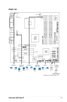
P5GDC-V Deluxe PS/2KBMS T: Mouse B: Keyboard SPDIF_O1 SPDIF_O2 ATX12V KBPWR1 LGA775 CPU_FAN1 DDR2 DIMM_A1 (64 bit,240-pin module) DDR DIMM_A1 (64 bit,240-pin module) DDR DIMM_A2 (64 bit,240-pin module) DDR2 DIMM_B1 (64 bit,240-pin module) DDR DIMM_B1 (64 bit,240-pin module) DDR DIMM_B2 (64 bit,240-pin module) EATXPWR PARALLEL PORT USBPW34 USBPW12 VGA Bottom: USB1 USB2 Top: 1394 LAN_USB34 Top:Rear Speaker Out Center: Side Speaker Out Below: Center/Subwoofer Top:Line In Center:Line Out Below:Mic In PWR_FAN1 Marvell 88E8053 CHA_FAN2 Intel R MCH 915G P5GDC-V PCIEX16 PRI_IDE1 AAFP CMI9880 CD PCI1 PCI2 PCI3 PCIEX1_1 SB_PWR1 PCIEX1_2 TSB43AB22A COM2 IE1394_2 R Intel ICH6R CR2032 3V Lithium Cell CMOS Power CLRTC1 USB56 USB78 USBPW56 USBPW78 ITE 8212F PRI_RAID1 FLOPPY1 GAME1 KBPWR1 2 1 +5V 3 2 +5VSB (Default) USBPW12 USBPW34 2 1 +5V (Default) 3 2 +5VSB CLRTC1 12 23 Normal (Default) Clear CMOS USBPW56 USBPW78 12 23 +5V (Default) +5VSB PLED+ PLED+5V Ground Ground Speaker Intel FWH 4Mb Super I/O SEC_RAID1 CHA_FAN1 SATA3 SATA4 SATA1 SATA2 CHASSIS1 PANEL1 PANEL1 PLED SPEAKER IDE_LED+ IDE_LED- PWR Ground Reset Ground IDE_LED Reset PWRSW 2-10 Chapitre 2 : Informations sur le matériel
-
 1
1 -
2
-
3
-
4
-
5
-
6
-
7
-
8
-
9
-
10
-
11
-
12
-
13
-
14
-
15
-
16
-
17
-
18
-
19
-
20
-
21
-
22
-
23
-
24
-
25
-
26
-
27
-
28
-
29
-
30
-
31
-
32
-
33
-
34
-
35
-
36
-
37
-
38
-
 39
39 -
 40
40 -
 41
41 -
 42
42 -
 43
43 -
 44
44 -
 45
45 -
 46
46 -
 47
47 -
 48
48 -
 49
49 -
50
-
51
-
52
-
53
-
54
-
55
-
56
-
57
-
58
-
59
-
60
-
61
-
62
-
63
-
64
-
65
-
66
-
67
-
68
-
69
-
70
-
71
-
72
-
73
-
74
-
75
-
76
-
77
-
78
-
79
-
80
-
81
-
82
-
83
-
84
-
85
-
86
-
87
-
88
-
89
-
90
-
91
-
92
-
93
-
94
-
95
-
96
-
97
-
98
-
99
-
100
-
101
-
102
-
103
-
104
-
105
-
106
-
107
-
108
-
109
-
110
-
111
-
112
-
113
-
114
-
115
-
116
-
117
-
118
-
119
-
120
-
121
-
122
-
123
-
124
 |
 |
