Asus P5GPL Motherboard Installation Guide - Page 17
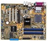
Instalação da CPU, Disposição da placa-principal
 |
View all Asus P5GPL manuals
Add to My Manuals
Save this manual to your list of manuals |
Page 17 highlights
1. Disposição da placa-principal PS/2KBMS KBPWR T: Mouse B: Keyboard SPDIF_O ATX12V LGA775 Super I/O DDR DIMM_A1 (64 bit,184-pin module) DDR DIMM_A2 (64 bit,184-pin module) DDR DIMM_B1 (64 bit,184-pin module) DDR DIMM_B2 (64 bit,184-pin module) PARALLEL PORT FLOPPY COM1 F_USB12 LAN_USB34 Top: Back surround L/R Center: Side surround L/R Below:Bass Top:Line In Center:Line Out Below:Mic In Marvell 88E8053 USBPW12 USBPW34 PWR_FAN PCIEX1_1 Intel R 915PL CPU_FAN PCIEX16 PCI1 CD P5GPL PCI2 ALC880 SPDIF_OUT PCI3 AAFP PCIEX1_2 CR2032 3V Lithium Cell CMOS Power Intel® ICH6 SATA2 SATA4 SATA1 SATA3 EATXPWR PRI_IDE 2. PCIEX1_3 USB56 USBPW56 USBPW78 CLRTC Intel FWH SB_PWR 4Mb CHASSIS USB78 CHA_FAN PANEL KBPWR 12 23 +5V +5VSB (Default) USBPW12 USBPW34 12 23 USBPW56 USBPW78 12 23 +5V +5VSB +5V +5VSB (Default) (Default) CLRTC 12 23 Normal (Default) Clear CMOS PLED+ PLED+5V Ground Ground Speaker PANEL PLED SPEAKER IDE_LED+ IDE_LED- PWR Ground Reset Ground Instalação da CPU IDE_LED Reset PWRSW Siga estas etapas para instalar um processador Intel® Pentium® 4 no socket 775. 1. Exerça pressão sobre a alavanca com o seu polegar (A) e de seguida mova-a para a esquerda (B) até ficar liberta da patilha de fixação. Patilha de fixação A Alavanca Tampa PnP Português ASUS P5GPL Este lado da "cam box" deve ficar voltada para si. 17
-
 1
1 -
2
-
3
-
4
-
5
-
6
-
7
-
8
-
9
-
10
-
11
-
 12
12 -
 13
13 -
 14
14 -
 15
15 -
 16
16 -
 17
17 -
 18
18 -
 19
19 -
 20
20
 |
 |
