Asus P5LD2 P5LD2 User's Manual for English Edition
Asus P5LD2 Manual
 |
View all Asus P5LD2 manuals
Add to My Manuals
Save this manual to your list of manuals |
Asus P5LD2 manual content summary:
- Asus P5LD2 | P5LD2 User's Manual for English Edition - Page 1
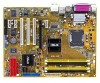
P5LD2 Motherboard - Asus P5LD2 | P5LD2 User's Manual for English Edition - Page 2
Product warranty or service will not be extended if: (1) the product is repaired, modified or altered, unless such repair, modification of alteration is authorized in writing by ASUS; or (2) the serial number of the product is defaced or missing. ASUS PROVIDES THIS MANUAL "AS IS" WITHOUT WARRANTY - Asus P5LD2 | P5LD2 User's Manual for English Edition - Page 3
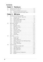
2-2 2.2.2 Screw holes 2-2 2.2.3 Motherboard layout 2-3 2.2.4 Layout contents 2-4 2.3 Central Processing Unit (CPU 2-6 2.3.1 Installing the CPU 2-6 2.3.2 Installing the CPU heatsink and fan 2-9 2.3.3 Uninstalling the CPU heatsink and fan 2-11 2.4 System memory 2-13 2.4.1 Overview 2-13 - Asus P5LD2 | P5LD2 User's Manual for English Edition - Page 4
BIOS 2 utility 4-5 4.1.4 ASUS EZ Flash utility 4-7 4.1.5 ASUS Update utility 4-8 4.2 BIOS setup program 4-11 4.2.2 Menu bar 4-12 4.2.3 Navigation keys 4-12 4.2.1 BIOS menu screen 4-12 4.2.4 Menu items 4-13 4.2.5 Sub-menu items 4-13 4.2.6 Configuration fields 4-13 4.2.7 Pop-up window CPU - Asus P5LD2 | P5LD2 User's Manual for English Edition - Page 5
5.2.1 Running the support CD 5-1 5.2.2 Drivers menu 5-2 5.2.3 Makedisk menu 5-3 5.2.3 Utilities menu 5-4 5.2.4 Manuals menu 5-5 5.2.5 Contact information 5-6 5.2.6 Other information 5-6 5.3 Software information 5-9 5.3.1 ASUS MyLogo 5-9 5.3.2 AI NET2 5-11 5.3.3 Audio configurations 5-12 - Asus P5LD2 | P5LD2 User's Manual for English Edition - Page 6
. This equipment generates, uses and can radiate radio frequency energy and, if not installed and used in accordance with manufacturer's instructions, may cause harmful interference to radio communications. However, there is no guarantee that interference will not occur in a particular installation - Asus P5LD2 | P5LD2 User's Manual for English Edition - Page 7
signal cables from the motherboard, ensure that all service technician or your retailer. Operation safety • Before installing the motherboard and adding devices on it, carefully read all the manuals screws, and staples away from connectors, slots, sockets and circuitry. • Avoid dust, humidity, and - Asus P5LD2 | P5LD2 User's Manual for English Edition - Page 8
The Appendix describes the CPU features that the motherboard supports. Where to find more information Refer to the following sources for additional information and for product and software updates. 1. ASUS websites The ASUS website provides updated information on ASUS hardware and software products - Asus P5LD2 | P5LD2 User's Manual for English Edition - Page 9
following symbols used throughout this manual. D A N G E R / W A R N I N G : Information to prevent injury to yourself when trying to complete a task. C A U T I O N : Information to prevent damage to the components when trying to complete a task. I M P O R T A N T : Instructions that you MUST follow - Asus P5LD2 | P5LD2 User's Manual for English Edition - Page 10
P5LD2 specifications summary CPU Chipset Front Side Bus Memory Expansion slots Storage High Definition Audio USB LAN Overclocking features LGA775 socket for Intel® Pentium® 4 processor Compatible with Intel® PCG 05B/05A and 04B/04A and the latest Intel® Smithfield dual-core processor Supports - Asus P5LD2 | P5LD2 User's Manual for English Edition - Page 11
Tweaker supports: • 8-step DRAM voltage control • Adjustable CPU core voltage at 0.0125 V increment • Adjustable PCI Express frequency from 90 MHz up to 150 MHz at 1 MHz increment • Stepless Frequency Selection (SFS) from 100 MHz up to 450 MHz at 1 MHz increment ASUS Q-Fan ASUS CrashFree BIOS 2 ASUS - Asus P5LD2 | P5LD2 User's Manual for English Edition - Page 12
P5LD2 specifications summary Support CD contents Device drivers ASUS PC Probe II ASUS Update ASUS AI Booster Microsoft® DirectX Anti-Virus Utility Adobe Acrobat Reader ASUS Screensaver *Specifications are subject to change without notice. xii - Asus P5LD2 | P5LD2 User's Manual for English Edition - Page 13
This chapter describes the motherboard features and the new technologies it supports. 1Product introduction - Asus P5LD2 | P5LD2 User's Manual for English Edition - Page 14
Chapter summary 1 1.1 Welcome 1-1 1.2 Package contents 1-1 1.3 Special features 1-2 ASUS P5LD2 - Asus P5LD2 | P5LD2 User's Manual for English Edition - Page 15
package with the list below. 1.2 Package contents Check your motherboard package for the following items. Motherboard ASUS P5LD2 motherboard I/O modules Cables shield ASUS motherboard support CD User guide If any of the above items is damaged or missing, contact your retailer. ASUS P5LD2 - Asus P5LD2 | P5LD2 User's Manual for English Edition - Page 16
processor, dual-channel memory, and PCI Express interfaces. The Intel® ICH7R Southbridge represents the seventh generation I/O controller hub that provides the interface for the storage, I/O, PCI Express, and 8-channel high definition audio interfaces. DDR2 memory support The motherboard supports - Asus P5LD2 | P5LD2 User's Manual for English Edition - Page 17
The motherboard supports the S/PDIF technology through the coaxial and optical S/PDIF Out ports on the rear panel. The S/PDIF technology turns your computer into a high-end entertainment system with digital connectivity to powerful audio and speaker systems. See pages 2-23 for details. ASUS P5LD2 - Asus P5LD2 | P5LD2 User's Manual for English Edition - Page 18
with USB 1.1. See pages 2-23 and 2-28 for details. Gigabit LAN solution The motherboard comes with a PCI Express Gigabit LAN controller to provide a total solution for your networking needs. The Gigabit LAN controller uses the PCI Express segment to provide faster data bandwidth. See pages 2-22, and - Asus P5LD2 | P5LD2 User's Manual for English Edition - Page 19
to 100 meters at 1 meter accuracy. See pages 4-23 and 5-11 for details. Fanless Design The ASUS fanless design allows multi-directional heat flow from major thermal sources in the motherboard to lower overall system temperature, resulting in quieter operation and longer system life. ASUS P5LD2 1-5 - Asus P5LD2 | P5LD2 User's Manual for English Edition - Page 20
feature allows you to restore the original BIOS data from the support CD in case when the BIOS codes and data are corrupted. This protection eliminates the need to buy a replacement ROM chip. See page 4-5 for details. ASUS Q-Fan technology The ASUS Q-Fan technology smartly adjusts the fan speeds - Asus P5LD2 | P5LD2 User's Manual for English Edition - Page 21
This chapter lists the hardware setup procedures that you have to perform when installing system components. It includes description of the jumpers and connectors on the motherboard. 2 Hardware information - Asus P5LD2 | P5LD2 User's Manual for English Edition - Page 22
Chapter summary 2 2.1 Before you proceed 2-1 2.2 Motherboard overview 2-2 2.3 Central Processing Unit (CPU 2-6 2.4 System memory 2-13 2.5 Expansion slots 2-17 2.6 Jumpers 2-20 2.7 Connectors 2-22 ASUS P5LD2 - Asus P5LD2 | P5LD2 User's Manual for English Edition - Page 23
you install motherboard components or change any motherboard settings. • Unplug the power cord from the wall socket before touching motherboard component. The illustration below shows the location of the onboard LED. P5LD2 ® P5LD2 Onboard LED SB_PWR ON Standby Power OFF Powered Off ASUS P5LD2 - Asus P5LD2 | P5LD2 User's Manual for English Edition - Page 24
or removing the motherboard. Failure to do so can cause you physical injury and damage motherboard components. 2.2.1 Placement direction When installing the motherboard, make sure indicated by circles to secure the motherboard to the chassis. Do not overtighten the screws! Doing so can damage the - Asus P5LD2 | P5LD2 User's Manual for English Edition - Page 25
30.5cm (12.0in) 2.2.3 Motherboard layout PS/2KBMS T: Mouse B: Keyboard SPDIF_O1 bit,240-pin module) DDR2 DIMM_A2 (64 bit,240-pin module) EATXPWR P5LD2 COM1 USB12 USBPW34 USBPW12 LGA775 LAN_USB34 Top: Back surround L/R Center: Side surround L/R Below:Bass Top ITE 8211F CHA_FAN1 ASUS P5LD2 2-3 - Asus P5LD2 | P5LD2 User's Manual for English Edition - Page 26
2.2.4 Layout contents Slots 1. DDR2 DIMM slots 2. PCI slots 3. PCI Express slot Jumpers 1. Clear RTC RAM (3-pin CLRTC) 2. USB Device wake-up (3-pin USBPW12, USBPW34, USBPW56, USBPW78) 3. Keyboard power (3-pin KBPWR) Rear panel connectors 1. PS/2 mouse port (green) 2. Parallel port 3. LAN ( - Asus P5LD2 | P5LD2 User's Manual for English Edition - Page 27
6. Front panel audio connector (10-1 pin AAFP) 7. USB connectors (10-1 pin USB56, USB78) 8. GAME/MIDI port connector (16-1 pin GAME) 9. CPU, Chassis, and -off button (Yellow 2-pin PWRSW) Reset button (Blue 2-pin RESET) Page 2-24 2-24 2-25 2-25 2-27 2-27 2-28 2-28 2-29 2-29 2-30 2-31 ASUS P5LD2 2-5 - Asus P5LD2 | P5LD2 User's Manual for English Edition - Page 28
LGA775 socket. • The product warranty does not cover damage to the socket contacts resulting from incorrect CPU installation/removal, or misplacement/loss/incorrect removal of the PnP cap. 2.3.1 Installing the CPU To install a CPU: 1. Locate the CPU socket on the motherboard. ® P5LD2 CPU Socket 775 - Asus P5LD2 | P5LD2 User's Manual for English Edition - Page 29
PnP cap B from the load plate window to remove (B). Load plate 5. Position the CPU over the socket, making sure that the gold triangle is on the bottom-left corner of the socket. The socket alignment A l i g n m e n t k e y key should fit into the CPU notch. Gold triangle mark ASUS P5LD2 A 2-7 - Asus P5LD2 | P5LD2 User's Manual for English Edition - Page 30
the CPU into the socket to prevent bending the connectors on the socket and damaging the CPU! 6. Close the load plate (A), then A push the load lever (B) until it snaps into the retention tab. B The motherboard supports Intel® Pentium® 4 LGA775 processors with the Intel® Enhanced Memory 64 - Asus P5LD2 | P5LD2 User's Manual for English Edition - Page 31
heatsink and fan assembly such that the CPU fan cable is closest to the CPU fan connector. Narrow end of the groove Motherboard hole Fastener Make sure to orient each fastener with the narrow end of the groove pointing outward. (The photo shows the groove shaded for emphasis.) ASUS P5LD2 2-9 - Asus P5LD2 | P5LD2 User's Manual for English Edition - Page 32
and fan B assembly in place. A A A B B B A 3. Connect the CPU fan cable to the connector on the motherboard labeled CPU_FAN. CPU_FAN P5LD2 GND CPU FAN PWR CPU FAN IN CPU FAN PWM ® P5LD2 CPU fan connector Do not forget to connect the CPU fan connector! Hardware monitoring errors can occur - Asus P5LD2 | P5LD2 User's Manual for English Edition - Page 33
motherboard. 2. Rotate each fastener counterclockwise. 3. Pull up two fasteners at a time in a diagonal sequence to disengage the heatsink and fan B assembly from the A motherboard. A B A B B A 4. Carefully remove the heatsink and fan assembly from the motherboard. ASUS P5LD2 2-11 - Asus P5LD2 | P5LD2 User's Manual for English Edition - Page 34
narrow end of the groove should point outward after resetting. (The photo shows the groove shaded for emphasis.) Narrow end of the groove Refer to the documentation in the boxed or stand-alone CPU fan package for detailed information on CPU fan installation. 2-12 Chapter 2: Hardware information - Asus P5LD2 | P5LD2 User's Manual for English Edition - Page 35
List on the next page for details. • Due to chipset resource allocation, the system may detect less than 4 GB system memory when you installed four 1 GB DDR2 memory modules. • This motherboard does not support memory modules made up of 128 Mb chips or double sided x16 memory modules. ASUS P5LD2 - Asus P5LD2 | P5LD2 User's Manual for English Edition - Page 36
Qualified Vendors Lists (QVL) DDR2-533 Size Vendor Model DIMM support C L Brand Side(s) Component A B C 512 MB SAMSUNG M378T6553BG0-CD5 N/A N/A SS K4T51083QB-GCD5 • • • 256 MB SAMSUNG M378T3253FG0-CD5 4 N/A SS K4T56083QF-GCD5 • • • 512 MB SAMSUNG M378T6453FG0-CD5 4 N/A DS - Asus P5LD2 | P5LD2 User's Manual for English Edition - Page 37
the yellow slots or the black slots as one pair of Dual-channel memory configuration. C - Supports two pairs of modules inserted into the yellow and black slots as two pairs of Dual-channel memory configuration. Visit the ASUS website for the latest DDR2-677/533/400 MHz QVL. ASUS P5LD2 2-15 - Asus P5LD2 | P5LD2 User's Manual for English Edition - Page 38
motherboard and the components. To install a DIMM: 1. Unlock a DIMM socket by pressing the retaining clips outward. 2. Align a DIMM on the socket into a socket to avoid damaging the DIMM. • The DDR2 DIMM sockets do not support DDR DIMMs. DO not install DDR DIMMs to the DDR2 DIMM sockets. 2.4.4 - Asus P5LD2 | P5LD2 User's Manual for English Edition - Page 39
cover (if your motherboard is already installed in drivers support "Share IRQ" or that the cards do not need IRQ assignments. Otherwise, conflicts will arise between the two PCI groups, making the system unstable and the card inoperable. Refer to the table on the next page for details. ASUS P5LD2 - Asus P5LD2 | P5LD2 User's Manual for English Edition - Page 40
Onboard USB controller 1 - shared - - - - - - Onboard USB controller 2 - - shared - - - - - Onboard USB controller 3 - - - shared - - - - Onboard EHCI controller shared Onboard IDE port - - - - - - shared - Onboard SATA port - shared - - - - - - Onboard Audio controller shared Onboard - Asus P5LD2 | P5LD2 User's Manual for English Edition - Page 41
card installed on the PCI Express x16 slot. 2.5.6 PCI Express x1 slot This motherboard supports PCI Express x1 network cards, SCSI cards and other cards that comply with the PCI Express specifications. The following figure shows a network card installed on the PCI Express x1 slot. ASUS P5LD2 2-19 - Asus P5LD2 | P5LD2 User's Manual for English Edition - Page 42
® P5LD2 Clear RTC RAM CLRTC 12 23 Normal (Default) Clear CMOS You do not need to clear the RTC when the system hangs due to overclocking. For system failure due to overclocking, use the C.P.R. (CPU Parameter Recall) feature. Shut down and reboot the system so the BIOS can automatically reset - Asus P5LD2 | P5LD2 User's Manual for English Edition - Page 43
. Set to +5VSB to wake up from S3 and S4 sleep modes (no power to CPU, DRAM in slow refresh, power supply in reduced power mode). The USBPWR12 and USBPWR34 jumpers , and a corresponding setting in the BIOS. KBPWR 12 23 +5V +5VSB (Default) P5LD2 ® P5LD2 Keyboard power setting ASUS P5LD2 2-21 - Asus P5LD2 | P5LD2 User's Manual for English Edition - Page 44
connects the center/subwoofer speakers. 6 . L i n e I n p o r t ( l i g h t b l u e ) . This port connects a tape, CD, DVD player, or other audio sources. 7 . L i n e O u t p o r t ( l i m e ) . This port connects a headphone or a speaker. In 4-channel, 6-channel, and 8-channel configuration, the - Asus P5LD2 | P5LD2 User's Manual for English Edition - Page 45
an external audio output device via an optical S/PDIF cable. 1 4 . C o a x i a l S / P D I F O u t p o r t . This port connects an external audio output device via a coaxial S/PDIF cable. 1 5 . P S / 2 k e y b o a r d p o r t ( p u r p l e ) . This port is for a PS/2 keyboard. ASUS P5LD2 2-23 - Asus P5LD2 | P5LD2 User's Manual for English Edition - Page 46
[red]) These connectors are for Ultra ATA 133/100/66 signal cables. The ITE IDE connectors support up to four IDE hard disk drives for easier data storage and data transfer. P5LD2 ® P5LD2 RAID connectors SEC_EIDE PIN 1 PRI_EIDE PIN 1 NOTE: Orient the red markings (usually zigzag) on the IDE - Asus P5LD2 | P5LD2 User's Manual for English Edition - Page 47
cable has three connectors: a blue connector for the primary IDE connector on the motherboard, a black connector for an Ultra DMA 100/66 IDE slave device (optical onboard Intel® ICH7R RAID controller. Refer to Chapter 5 for details on how to set up Serial ATA RAID configurations. ASUS P5LD2 2-25 - Asus P5LD2 | P5LD2 User's Manual for English Edition - Page 48
BIOS P5LD2 SATA3 SATA1 GND RSATA_TXP3 RSATA_TXN3 GND RSATA_RXP3 RSATA_RXN3 GND SATA2 GND RSATA_TXP1 RSATA_TXN1 GND RSATA_RXP1 RSATA_RXN1 GND GND RSATA_TXP2 RSATA_TXN2 GND RSATA_RXP2 RSATA_RXN2 GND Important notes on Serial ATA • You must install Windows® 2000 Service Pack 4 or the Windows® XP - Asus P5LD2 | P5LD2 User's Manual for English Edition - Page 49
motherboard high-definition audio capability. • By default, this connector is set to HD Audio. If you want to connect a legacy AC'97 front panel audio module to this connector, set the F r o n t P a n e l S u p p o r t T y p e item in the BIOS Setup to [AC'97]. See page 4-29 for details. ASUS P5LD2 - Asus P5LD2 | P5LD2 User's Manual for English Edition - Page 50
specification that supports up to 480 Mbps connection speed. P5LD2 USB+5V USB_P8USB_P8+ GND NC USB+5V USB_P6USB_P6+ GND NC ® P5LD2 USB 2.0 and MIDI devices for playing or editing audio files. P5LD2 +5V J2B1 J2CX MIDI_OUT J2CY J2B2 MIDI_IN ® P5LD2 Game connector GAME +5V J1B1 J1CX GND - Asus P5LD2 | P5LD2 User's Manual for English Edition - Page 51
on the fan connectors! GND CPU FAN PWR CPU FAN IN CPU FAN PWM CPU_FAN PWR_FAN CHA_FAN2 CPU_FAN PWR_FAN GND +12V Rotation P5LD2 ® CHA_FAN1 CHA_FAN2 CHA_FAN1 GND +12V Rotation Rotation +12V GND P5LD2 Fan connectors Only the CPU_FAN connector supports the ASUS Q-Fan feature. 10. Chassis - Asus P5LD2 | P5LD2 User's Manual for English Edition - Page 52
with more power consuming devices. The system may become unstable or may not boot up if the power is inadequate. ATX12V EATXPWR P5LD2 +12V DC GND ® P5LD2 ATX power connectors +12V DC +3 Volts GND +12 Volts +12 Volts +5V Standby Power OK Ground +5 Volts Ground +5 Volts Ground +3 Volts +3 Volts - Asus P5LD2 | P5LD2 User's Manual for English Edition - Page 53
hear system beeps and BIOS settings. Pressing the power switch for more than four seconds while the system is ON turns the system OFF. • Reset button (Blue 2-pin RESET) This 2-pin connector is for the chassis-mounted reset button for system reboot without turning off the system power. ASUS P5LD2 - Asus P5LD2 | P5LD2 User's Manual for English Edition - Page 54
2-32 Chapter 2: Hardware information - Asus P5LD2 | P5LD2 User's Manual for English Edition - Page 55
This chapter describes the power up Powerin3g up sequence, the vocal POST messages, and ways of shutting down the system. - Asus P5LD2 | P5LD2 User's Manual for English Edition - Page 56
Chapter summary 3 3.1 Starting up for the first time 3-1 3.2 Powering off the computer 3-2 ASUS P5LD2 - Asus P5LD2 | P5LD2 User's Manual for English Edition - Page 57
continuous beeps followed by four short beeps Error Keyboard controller error Refresh Time error No master drive detected Floppy controller failure Hardware component failure 7. At power on, hold down the key to enter the BIOS Setup. Follow the instructions in Chapter 4. ASUS P5LD2 3-1 - Asus P5LD2 | P5LD2 User's Manual for English Edition - Page 58
to shut down the computer. 3. The power supply should turn off after Windows® shuts down. If you are using Windows® XP: 1. Click the S t a r t button then select T u BIOS setting. Pressing the power switch for more than four seconds lets the system enter the soft-off mode regardless of the BIOS - Asus P5LD2 | P5LD2 User's Manual for English Edition - Page 59
This chapter tells how to change the system settings through the BIOS Setup menus. Detailed descriptions of the BIOS parameters are also provided. 4 BIOS setup - Asus P5LD2 | P5LD2 User's Manual for English Edition - Page 60
Chapter summary 4 4.1 Managing and updating your BIOS 4-1 4.2 BIOS setup program 4-11 4.3 Main menu 4-14 4.4 Advanced menu 4-19 4.5 Power menu 4-33 4.6 Boot menu 4-38 4.7 Exit menu 4-43 ASUS P5LD2 - Asus P5LD2 | P5LD2 User's Manual for English Edition - Page 61
motherboard BIOS using the ASUS Update or AFUDOS utilities. 4.1.1 Creating a bootable floppy disk 1. Do either one of the following to create a bootable floppy disk. DOS environment a. Insert a 1.44MB floppy disk into the drive. b. At the DOS prompt, type format A:/S then press . Windows® XP - Asus P5LD2 | P5LD2 User's Manual for English Edition - Page 62
optical drive letter. e. Press , then follow screen instructions to continue. 2. Copy the original or the latest motherboard BIOS file to the bootable floppy disk. 4.1.2 AFUDOS utility The AFUDOS utility allows you to update the BIOS file in DOS environment using a bootable floppy disk with - Asus P5LD2 | P5LD2 User's Manual for English Edition - Page 63
(afudos.exe) from the motherboard support CD to the bootable floppy disk you created earlier. 3. Boot the system in DOS mode, then at the prompt type: afudos /i[filename] where [filename] is the latest or the original BIOS file on the bootable floppy disk. A:\>afudos /iP5LD2.rom ASUS P5LD2 4-3 - Asus P5LD2 | P5LD2 User's Manual for English Edition - Page 64
reset the system while updating the BIOS to prevent system boot failure! 5. The utility returns to the DOS prompt after the BIOS update process is completed. Reboot the system from the hard disk drive. A:\>afudos /iP5LD2.rom AMI Firmware Update Utility - Version 1.19(ASUS V2 - Asus P5LD2 | P5LD2 User's Manual for English Edition - Page 65
BIOS recovery... Checking for floppy... Floppy found! Reading file "P5LD2.ROM". Completed. Start flashing... DO NOT shut down or reset the system while updating the BIOS! Doing so can cause system boot failure! 4. Restart the system after the utility completes the updating process. ASUS P5LD2 - Asus P5LD2 | P5LD2 User's Manual for English Edition - Page 66
down or reset the system while updating the BIOS! Doing so can cause system boot failure! 4. Restart the system after the utility completes the updating process. The recovered BIOS may not be the latest BIOS version for this motherboard. Visit the ASUS website (www.asus.com) to download the latest - Asus P5LD2 | P5LD2 User's Manual for English Edition - Page 67
Alt> + during the Power-On Self Tests (POST). To update the BIOS using EZ Flash: 1. Visit the ASUS website (www.asus.com) to download the latest BIOS file for the motherboard and rename the same to P 5 L D 2 . R O M. 2. Save the BIOS file to a floppy disk, then restart the system. 3. Press - Asus P5LD2 | P5LD2 User's Manual for English Edition - Page 68
you to manage, save, and update the motherboard BIOS in Windows® environment. The ASUS Update utility allows you to: • Save the current BIOS file • Download the latest BIOS file from the Internet • Update the BIOS from an updated BIOS file • Update the BIOS directly from the Internet, and • View - Asus P5LD2 | P5LD2 User's Manual for English Edition - Page 69
S U p d a t e. The ASUS Update main window appears. 2. Select U p d a t e B I O S f r o m 3. Select the ASUS FTP site t h e I n t e r n e t option from the nearest you to avoid network drop-down menu, then click traffic, or click A u t o S e l e c t. N e x t. Click N e x t. ASUS P5LD2 4-9 - Asus P5LD2 | P5LD2 User's Manual for English Edition - Page 70
to download. Click N e x t. 5. Follow the screen instructions to complete the update process. The ASUS Update utility is capable of updating itself through the Internet. Always update the utility to avail all its features. Updating the BIOS through a BIOS file To update the BIOS through a BIOS file - Asus P5LD2 | P5LD2 User's Manual for English Edition - Page 71
under the Exit Menu. See section "4.7 Exit Menu." • The BIOS setup screens shown in this section are for reference purposes only, and may not exactly match what you see on your screen. • Visit the ASUS website (www.asus.com) to download the latest BIOS file for this motherboard. ASUS P5LD2 4-11 - Asus P5LD2 | P5LD2 User's Manual for English Edition - Page 72
Master Fourth IDE Slave IDE Configuration System Information [11:51:19] [Thu 05/07/2004] [1.44M, 3.5 in] : [ST320413A] : [ASUS CD-S520/A] : [Not Detected] : [Not Detected] : [Not Detected] : [Not Detected] Use [ENTER], [TAB] or [ keys differ from one screen to another. 4-12 Chapter 4: BIOS setup - Asus P5LD2 | P5LD2 User's Manual for English Edition - Page 73
a list of options. Refer to "4.2.7 Pop-up window." 4.2.7 Pop-up window Select a menu item then press to display a pop-up window with the system to malfunction. Configure DRAM Timing by SPD Memory Acceleration Mode DRAM Idle Timer DRAm Refresh Rate [ up window Scroll bar ASUS P5LD2 4-13 - Asus P5LD2 | P5LD2 User's Manual for English Edition - Page 74
an overview of the basic system information. Refer to section "4.2.1 BIOS menu screen" for information on the menu screen items and how Information [11:51:19] [Thu 05/07/2004] [1.44M, 3.5 in] : [ST320413A] : [ASUS CD-S520/A] : [Not Detected] : [Not Detected] : [Not Detected] : [Not Detected] Use - Asus P5LD2 | P5LD2 User's Manual for English Edition - Page 75
General Help F10 Save and Exit ESC Exit The BIOS automatically detects the values opposite the dimmed items ( supports multi-sector transfer feature. When set to [Disabled], the data transfer from and to the device occurs one sector at a time. Configuration options: [Disabled] [Auto] ASUS P5LD2 - Asus P5LD2 | P5LD2 User's Manual for English Edition - Page 76
mode SATA controller is forced to Native mode. Configure SATA As [Standard IDE] Sets the configuration for the Serial ATA connectors supported by the Southbridge chip. The AHCI allows the onboard storage driver to Serial ATA hard disk drives, set this item to [RAID]. 4-16 Chapter 4: BIOS setup - Asus P5LD2 | P5LD2 User's Manual for English Edition - Page 77
support/chipsets/imst/sb/CS-012304.htm www.intel.com/support/chipsets/imst/sb/CS-012305.htm The SATA controller Windows® 2000/XP. Configuration options: [Disabled] [Compatible Mode] [Enhanced Mode] Enhanced Mode Support options and encountered problems, revert to the set to [RAID]. ASUS P5LD2 4-17 - Asus P5LD2 | P5LD2 User's Manual for English Edition - Page 78
: 1024MB Select Screen Select Item +- Change Option F1 General Help F10 Save and Exit ESC Exit AMI BIOS Displays the auto-detected BIOS information. Processor Displays the auto-detected CPU specification. System Memory Displays the auto-detected total, appropriated (in use), and available system - Asus P5LD2 | P5LD2 User's Manual for English Edition - Page 79
to select the overclocking options to achieve the desired CPU internal frequency. Select either one of the preset overclocking the ASUS AI Non-delay Overclocking System feature intelligently determines the system load and automatically boost the performance for the most demanding tasks. ASUS P5LD2 - Asus P5LD2 | P5LD2 User's Manual for English Edition - Page 80
when you set the A I O v e r c l o c k i n g item to [Manual]. CPU Frequency [XXX] Displays the frequency sent by the clock generator to the system bus and PCI bus. The value of this item is auto-detected by the BIOS. Use the < + > and < - > keys to adjust the CPU frequency. You can also type the - Asus P5LD2 | P5LD2 User's Manual for English Edition - Page 81
the DDR2 documentation before adjusting the memory voltage. Setting a very high memory voltage may damage the memory module(s)! CPU VCore Voltage [Auto] Allows you to select the CPU VCore voltage. Configuration options: ! We recommend that you set these items to the default [Auto]. ASUS P5LD2 4-21 - Asus P5LD2 | P5LD2 User's Manual for English Edition - Page 82
O . S . M o d e item is set to [Manual]. Sensitivity [Sensitive] Allows you to select the sensitivity of the AI NOS sensor. Refer to the description of the configuration options below. N o r m a l - overclocking is activated depending on the CPU loading. S e n s i t i v e - overclocking is activated - Asus P5LD2 | P5LD2 User's Manual for English Edition - Page 83
enabled, the menu reports the cable faults or shorts, and displays the point (length) where the fault or short is detected. Configuration options: [Disabled] [Enabled] ASUS P5LD2 4-23 - Asus P5LD2 | P5LD2 User's Manual for English Edition - Page 84
an item then press to display the configuration options. USB Configuration Module Version - 2.23.2-9.4 USB Devices Enabled: None USB Function Legacy USB Support USB 2.0 Controller USB 2.0 Controller Mode BIOS EHCI Hand-Off [Enabled] [Auto] [Enabled] [HiSpeed] [Disabled] Enables USB host - Asus P5LD2 | P5LD2 User's Manual for English Edition - Page 85
automatically reduce the CPU multiplier value for more flexibility when increasing the external FSB. Configuration options: [Auto] [Disabled] [Enabled] Microcode Updation [Enabled] Allows you to enable or disable the microcode updation. Configuration options: [Disabled] [Enabled] ASUS P5LD2 4-25 - Asus P5LD2 | P5LD2 User's Manual for English Edition - Page 86
support this function. Enhanced C1 Control [Auto] When set to [Auto], the BIOS automatically checks the CPU's capability to enable the C1E support. In C1E mode, the CPU for details on how to use the EIST feature. • The motherboard comes with a BIOS file that supports EIST. • When A I Q u i e t is - Asus P5LD2 | P5LD2 User's Manual for English Edition - Page 87
Booting Graphic Adapter Priori PEG Buffer Length Link Latency PEG Root Control PEG Link Mode Slot Power High Priority Port Select [Enabled (Serial Presence Detect). When disabled, you can manually set the DRAM timing parameters through the DRAM sub ] [4 Clocks] [5 Clocks] [6 Clocks] ASUS P5LD2 4-27 - Asus P5LD2 | P5LD2 User's Manual for English Edition - Page 88
, or set to automatic the PCI Express graphics card root control. Configuration options: [Auto] [Disabled] [Enabled] PEG Link Mode [Auto] Sets the PCI Express graphics link mode. Setting this item to [Auto] allows the motherboard to automatically adjust the PCI Express graphics link mode to the - Asus P5LD2 | P5LD2 User's Manual for English Edition - Page 89
options: [AC97] [HD Audio] OnBoard PCIEX GbE LAN [Enabled] Allows you to enable or disable the onboard PCI Express Gigabit LAN controller. Configuration options: [Disabled] [Enabled] The Gigabit LAN controller does not support S5 Wake-On-LAN function under DOS mode or Windows® ME. LAN Option ROM - Asus P5LD2 | P5LD2 User's Manual for English Edition - Page 90
Detecting Device Time [Quick Mode] Sets the time the ITE8211F IDE controller detects devices connected to the IDE connectors. This item appears only when the I T E 8 2 1 1 F C o n t r o l l e r is set options: [Disabled] [200/300] [200/330] [208/300] [208/330] 4-30 Chapter 4: BIOS setup - Asus P5LD2 | P5LD2 User's Manual for English Edition - Page 91
resources for either PCI/PnP or legacy ISA devices, and setting the memory size block for legacy ISA devices. Take caution when changing the settings and Exit ESC Exit Plug And Play O/S [No] When set to [No], BIOS configures all the devices in the system. When set to [Yes] and if ] ASUS P5LD2 4-31 - Asus P5LD2 | P5LD2 User's Manual for English Edition - Page 92
IRQ-xx assigned to [PCI Device] When set to [PCI Device], the specific IRQ is free for use of PCI/PnP devices. When set to [Reserved], the IRQ is reserved for legacy ISA devices. Configuration options: [PCI Device] [Reserved] 4-32 Chapter 4: BIOS setup - Asus P5LD2 | P5LD2 User's Manual for English Edition - Page 93
[Enabled] Allows you to enable or disable the Advanced Programmable Interrupt Controller (APIC) mode under Advanced Configuration and Power Interface (ACPI). When enabled, the ACPI APIC table pointer is included in the RSDT pointer list. Configuration options: [Disabled] [Enabled] ASUS P5LD2 4-33 - Asus P5LD2 | P5LD2 User's Manual for English Edition - Page 94
Alarm Hour To set the alarm hour, highlight this item and press the or key to make the selection. Configuration options: [00] [1]... ~ [23] 4-34 Chapter 4: BIOS setup - Asus P5LD2 | P5LD2 User's Manual for English Edition - Page 95
to turn on the system. This feature requires an ATX power supply that provides at least 1A on the +5VSB lead. Configuration options: [Disabled] [Enabled] ASUS P5LD2 4-35 - Asus P5LD2 | P5LD2 User's Manual for English Edition - Page 96
• And the C P U Q - F a n C o n t r o l item is enabled, the C P U F a n P r o f i l e M o d e item appears with the default setting [Optimal]. CPU Q-Fan Control [Disabled] Allows you to enable or disable the ASUS Q-Fan feature that smartly adjusts the fan speeds for more efficient system operation - Asus P5LD2 | P5LD2 User's Manual for English Edition - Page 97
[N/A] The onboard hardware monitor automatically detects and displays the CPU fan speed in rotations per minute (RPM). If the fan is not connected to the motherboard, the field shows N/A. Chassis Fan1 Speed (RPM) [ detects the voltage output through the onboard voltage regulators. ASUS P5LD2 4-37 - Asus P5LD2 | P5LD2 User's Manual for English Edition - Page 98
Device Priority 1st Boot Device 2nd Boot Device 3rd Boot Device [1st FLOPPY DRIVE] [PM-ST330620A] [PS-ASUS CD-S360] Select Screen Select Item Enter Go to Sub-screen F1 General Help F10 Save and Exit ESC Exit the system. Configuration options: [xxxxx Drive] [Disabled] 4-38 Chapter 4: BIOS setup - Asus P5LD2 | P5LD2 User's Manual for English Edition - Page 99
Lock PS/2 Mouse Support Wait For 'F1' If Error Hit 'DEL' Message Display Interrupt 19 Capture [Enabled] [Enabled] [Force BIOS] [On] [Auto] [Enabled] [Enabled] [Disabled] Allows BIOS to skip certain "Press DEL to run Setup" during POST. Configuration options: [Disabled] [Enabled] ASUS P5LD2 4-39 - Asus P5LD2 | P5LD2 User's Manual for English Edition - Page 100
the supervisor password, select the Change Supervisor Password then press . The message "Password Uninstalled" appears. If you forget your BIOS password, you can clear clear it by erasing the CMOS Real Time Clock (RTC) RAM. See section "2.6 Jumpers" for information on how to erase the RTC - Asus P5LD2 | P5LD2 User's Manual for English Edition - Page 101
. The message "Password Installed" appears after you set your password successfully. To change the user password, follow the same steps as in setting a user password. ASUS P5LD2 4-41 - Asus P5LD2 | P5LD2 User's Manual for English Edition - Page 102
Select this item to clear the user password. Password Check [Setup] When set to [Setup], BIOS checks for user password when accessing the Setup utility. When set to [Always], BIOS checks for user password both when accessing Setup and booting the system. Configuration options: [Setup] [Always - Asus P5LD2 | P5LD2 User's Manual for English Edition - Page 103
, the BIOS asks for a confirmation before exiting. Discard Changes Allows you to discard the selections you made and restore the previously saved values. After selecting this option, a confirmation appears. Select < O K > to discard any changes and load the previously saved values. ASUS P5LD2 4-43 - Asus P5LD2 | P5LD2 User's Manual for English Edition - Page 104
load the default values for each of the parameters on the Setup menus. When you select this option or if you press , a confirmation window appears. Select < O K > to load the default values. Select E x i t & S a v e C h a n g e s or make other changes before saving the values to the non-volatile - Asus P5LD2 | P5LD2 User's Manual for English Edition - Page 105
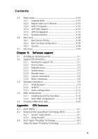
This chapter describes the contents of the support CD that comes with the motherboard package. 5 Software support - Asus P5LD2 | P5LD2 User's Manual for English Edition - Page 106
Chapter summary 5 5.1 Installing an operating system 5-1 5.2 Support CD information 5-1 5.3 Software information 5-9 5.4 RAID configurations 5-17 5.5 Creating a RAID driver disk 5-29 ASUS P5LD2 - Asus P5LD2 | P5LD2 User's Manual for English Edition - Page 107
that you install Windows® 2000 Service Pack 4 or the Windows® XP Service Pack1 or later versions before installing the drivers for better compatibility and system stability. 5.2 Support CD information The support CD that came with the motherboard package contains the drivers, software applications - Asus P5LD2 | P5LD2 User's Manual for English Edition - Page 108
the Quick Fix Engineering (QFE) driver updates. Intel Chipset Inf Update Program Installs the Intel® Chipset INF Update Program. This driver enables Plug-n-Play INF support for the Intel® chipset components on the motherboard. When installed to the target system, this driver provides the method for - Asus P5LD2 | P5LD2 User's Manual for English Edition - Page 109
RAID driver disk for a 32 or 64-bit system. Make ITE8211 32/64bit IDE Driver Disk Allows you to create an ITE8211 IDE driver disk for a 32 or 64-bit system. The S i l i c o n I m a g e S A T A / R A I D D r i v e r D i s k items are for ASUS P5WD2 Premium and P5LD2 Deluxe models only. ASUS P5LD2 - Asus P5LD2 | P5LD2 User's Manual for English Edition - Page 110
, CPU temperature, and system voltages, and alerts you of any detected problems. This utility helps you keep your computer in healthy operating condition. Refer to the online help for details. ASUS Update The ASUS Update utility that allows you to update the motherboard BIOS in Windows® environment - Asus P5LD2 | P5LD2 User's Manual for English Edition - Page 111
computer graphics and sounds. DirectX® improves the multimedia features of your computer so you can enjoy watching TV and movies, capturing videos, or playing games in your computer. AI Booster The ASUS AI Booster application allows you to overclock the CPU speed in Windows® environment. Anti-virus - Asus P5LD2 | P5LD2 User's Manual for English Edition - Page 112
t tab to display the ASUS contact information. You can also find this information on the inside front cover of this user guide. 5.2.6 Other information The icons on the top right corner of the screen provide additional information on the motherboard and the contents of the support CD. Click an icon - Asus P5LD2 | P5LD2 User's Manual for English Edition - Page 113
Browse this CD Displays the contents of the support CD in graphical format. Technical Support Form Displays the ASUS Technical Support Request Form that you have to fill out when requesting technical support. ASUS P5LD2 5-7 - Asus P5LD2 | P5LD2 User's Manual for English Edition - Page 114
Filelist Displays the contents of the support CD in text format. 5-8 Chapter 5: Software support - Asus P5LD2 | P5LD2 User's Manual for English Edition - Page 115
d a t e B I O S f r o m a f i l e from the drop down menu, then click N e x t. 5. When prompted, locate the new BIOS file, then click N e x t. The ASUS MyLogo window appears. 6. From the left window pane, select the folder that contains the image you intend to use as your boot logo. ASUS P5LD2 5-9 - Asus P5LD2 | P5LD2 User's Manual for English Edition - Page 116
7. When the logo images appear on the right window pane, select an image to enlarge by clicking on it. 8. Adjust the boot image to your desired size by selecting a value on the R a t i o box. 9. When the screen returns to the ASUS Update utility, flash the original BIOS to load the new boot logo. 10 - Asus P5LD2 | P5LD2 User's Manual for English Edition - Page 117
main window is disabled if no problem is detected on the LAN cable(s) connected to the LAN port(s). • If you want the system to check the status of the LAN cable before entering the OS, enable the item P o s t C h e c k L A N C a b l e in the BIOS Setup. See page 4-23 for details. ASUS P5LD2 5-11 - Asus P5LD2 | P5LD2 User's Manual for English Edition - Page 118
r from the support CD that came with the motherboard package. If the Realtek audio software is correctly installed, you will find the Realtek HD Audio Manager icon on HD Audio Manager. Realtek HD Audio Manager Realtek HD Audio Manager Configuration options Control settings window Exit button - Asus P5LD2 | P5LD2 User's Manual for English Edition - Page 119
( ) to display information about the audio driver version, DirectX version, audio controller, audio codec, and language setting. Minimize Click the minimize button ( ) to minimize the window. Exit Click the exit button ( ) to exit the Realtek HD Audio Manager. Configuration options Click any - Asus P5LD2 | P5LD2 User's Manual for English Edition - Page 120
sound effect options: 1. From the Realtek HD Audio Sound Effect settings and exit. Mixer The Mixer option allows you to configure audio output (playback) volume and audio input (record) volume. To set the mixer options: 1. From the Realtek HD Audio control - Asus P5LD2 | P5LD2 User's Manual for English Edition - Page 121
The control settings window displays the status of connected devices. Click for analog and digital options. 4. Click to effect the Audio I/O a t i o n option button to reduce the echo from the front speakers when recording. 4. Click to effect the Microphone settings and exit. ASUS P5LD2 5-15 - Asus P5LD2 | P5LD2 User's Manual for English Edition - Page 122
Audio Demo: 1. From the Realtek HD Audio Manager, click the 3 D A u d i o D e m o tab. 2. Click the option buttons to change the sound, moving path, or environment settings. 3. Click to test your settings. 4. Click to effect the 3D Audio Demo settings and exit. 5-16 Chapter 5: Software support - Asus P5LD2 | P5LD2 User's Manual for English Edition - Page 123
controller that allows you to configure Serial ATA hard disk drives as RAID sets. The motherboard supports driver from the support CD to a floppy disk before you install an operating system to the selected hard disk drive. Refer to section "5.6 Creating a RAID driver disk" for details. ASUS P5LD2 - Asus P5LD2 | P5LD2 User's Manual for English Edition - Page 124
b o a r d S e r i a l - A T A B O O T R O M, press , then select E n a b l e d from the options. 6. Save your changes, then exit the BIOS Setup. Refer to the system or the motherboard user guide for details on entering and navigating through the BIOS Setup. 5-18 Chapter 5: Software support - Asus P5LD2 | P5LD2 User's Manual for English Edition - Page 125
that are connected to the Serial ATA connectors supported by the Southbridge. To enter the Intel® Volume 2. Delete RAID Volume 3. Reset Disks to Non-RAID 4. Exit BIOS setup screens shown in this section are for reference only and may not exactly match the items on your screen. ASUS P5LD2 5-19 - Asus P5LD2 | P5LD2 User's Manual for English Edition - Page 126
arrow key to highlight a drive, then press to select. A small triangle marks the selected drive. Press after completing your selection. 5-20 Chapter 5: Software support - Asus P5LD2 | P5LD2 User's Manual for English Edition - Page 127
lower stripe size for server systems, and a higher stripe size for multimedia computer systems used mainly for audio and video editing. 7. Key in the RAID volume capacity that you want, then press . The default the main menu, or to go back to the Create Volume menu. ASUS P5LD2 5-21 - Asus P5LD2 | P5LD2 User's Manual for English Edition - Page 128
create this volume? (Y/N): 6. Press to create the RAID volume and return to main menu or to go back to Create Volume menu. 5-22 Chapter 5: Software support - Asus P5LD2 | P5LD2 User's Manual for English Edition - Page 129
systems, and a higher stripe size for multimedia computer systems used mainly for audio and video editing. 5. Key in the RAID volume capacity that you want then press when the C a p a c i t y item is highlighted. The default value indicates the maximum allowed capacity. ASUS P5LD2 5-23 - Asus P5LD2 | P5LD2 User's Manual for English Edition - Page 130
the RAID 5 set, then press . 3. When the R A I D L e v e l item is highlighted, press the up/down arrow key to select R A I D 5 ( P a r i t y ), then press . 5-24 Chapter 5: Software support - Asus P5LD2 | P5LD2 User's Manual for English Edition - Page 131
recommend a lower stripe size for server systems, and a higher stripe size for multimedia computer systems used mainly for audio and video editing. 7. Key in the RAID volume capacity that you want, then press when the C a p menu or to go back to the Create Volume menu. ASUS P5LD2 5-25 - Asus P5LD2 | P5LD2 User's Manual for English Edition - Page 132
2. Use the up/down arrow key to select the RAID set you want to delete, then press . This window appears. [ DELETE VOLUME VERIFICATION ] ALL DATA IN THE VOLUME WILL BE LOST! Are you sure you want to ; otherwise, press to return to the Delete Volume menu. 5-26 Chapter 5: Software support - Asus P5LD2 | P5LD2 User's Manual for English Edition - Page 133
Disk XX.XGB Member Disk Select the disks that should be reset. [↑↓]-Previous/Next [SPACE]-Selects [ENTER]-Selection Complete 2. Use This window appears. [ CONFIRM EXIT ] Are you sure you want to exit? (Y/N): 2. Press to exit or press to return to the utility main menu. ASUS P5LD2 5-27 - Asus P5LD2 | P5LD2 User's Manual for English Edition - Page 134
, then press to select. 3. Press to reset the RAID set drive. A confirmation window appears. 4. Press to reset the drive; otherwise, press to return to the utility main menu. 5. Follow steps 2 to 4 to select and reset other RAID set drives. 5-28 Chapter 5: Software support - Asus P5LD2 | P5LD2 User's Manual for English Edition - Page 135
in the support CD) or in Windows® environment. To create a RAID driver disk in DOS environment: 1. Place the motherboard support CD in the optical drive. 2. Restart the computer, then enter the BIOS Setup. 3. reference only, and may not exactly match the items on your screen. ASUS P5LD2 5-29 - Asus P5LD2 | P5LD2 User's Manual for English Edition - Page 136
virus infection. 10. Press any key to return to the Makedisk menu. To create a RAID driver disk in Windows® environment: 1. Place the motherboard support CD in the optical drive. 2. When the D r i v e r s menu appears, select the RAID driver disk you wish to create: • Click Make ICH7 32 bit RAID - Asus P5LD2 | P5LD2 User's Manual for English Edition - Page 137
CPU featAures The Appendix describes the CPU features that the motherboard supports. - Asus P5LD2 | P5LD2 User's Manual for English Edition - Page 138
Chapter summary A A.1 Intel® EM64T A-1 A.2 Enhanced Intel SpeedStep® Technology (EIST A-1 A.3 Intel® Hyper-Threading Technology A-3 ASUS P5LD2 - Asus P5LD2 | P5LD2 User's Manual for English Edition - Page 139
compatible with Intel® Pentium® 4 LGA775 processors running on 32-bit operating systems. • The motherboard comes with a BIOS file that supports EM64T. You can download the latest BIOS file from the ASUS website (www.asus.com/support/download/) if you need to update the BIOS file. See Chapter 4 for - Asus P5LD2 | P5LD2 User's Manual for English Edition - Page 140
: 1. Turn on the computer, then enter the BIOS Setup. 2. Go to the Advanced Menu, highlight CPU Configuration, then press . 3. Set the Intel . Close the Display Properties window. After you adjust the power scheme, the CPU internal frequency slightly decreases when the CPU loading is low. The - Asus P5LD2 | P5LD2 User's Manual for English Edition - Page 141
• The motherboard supports Intel® Pentium® 4 LGA775 processors with Hyper-Threading Technology. • Hyper-Threading Technology is supported under Windows® XP/2003 Server and Linux 2.4.x (kernel) and later versions only. Under Linux, use the Hyper-Threading compiler to compile the code. If you - Asus P5LD2 | P5LD2 User's Manual for English Edition - Page 142
A-4 Appendix: CPU features
-
 1
1 -
 2
2 -
 3
3 -
 4
4 -
 5
5 -
 6
6 -
 7
7 -
8
-
9
-
10
-
11
-
12
-
13
-
14
-
15
-
16
-
17
-
18
-
19
-
20
-
21
-
22
-
23
-
24
-
25
-
26
-
27
-
28
-
29
-
30
-
31
-
32
-
33
-
34
-
35
-
36
-
37
-
38
-
39
-
40
-
41
-
42
-
43
-
44
-
45
-
46
-
47
-
48
-
49
-
50
-
51
-
52
-
53
-
54
-
55
-
56
-
57
-
58
-
59
-
60
-
61
-
62
-
63
-
64
-
65
-
66
-
67
-
68
-
69
-
70
-
71
-
72
-
73
-
74
-
75
-
76
-
77
-
78
-
79
-
80
-
81
-
82
-
83
-
84
-
85
-
86
-
87
-
88
-
89
-
90
-
91
-
92
-
93
-
94
-
95
-
96
-
97
-
98
-
99
-
100
-
101
-
102
-
103
-
104
-
105
-
106
-
107
-
108
-
109
-
110
-
111
-
112
-
113
-
114
-
115
-
116
-
117
-
118
-
119
-
120
-
121
-
122
-
123
-
124
-
125
-
126
-
127
-
128
-
129
-
130
-
131
-
132
-
133
-
134
-
135
-
136
-
137
-
138
-
139
-
140
-
141
-
142
 |
 |

Motherboard
P5LD2