Asus P5MT-M User Guide
Asus P5MT-M Manual
 |
View all Asus P5MT-M manuals
Add to My Manuals
Save this manual to your list of manuals |
Asus P5MT-M manual content summary:
- Asus P5MT-M | User Guide - Page 1
Motherboard P5MT Series P5MT P5MT/SCSI - Asus P5MT-M | User Guide - Page 2
express written permission of ASUSTeK COMPUTER INC. ("ASUS"). Product warranty or service will not be extended if: (1) the ASUS HAS BEEN ADVISED OF THE POSSIBILITY OF SUCH DAMAGES ARISING FROM ANY DEFECT OR ERROR IN THIS MANUAL OR PRODUCT. SPECIFICATIONS AND INFORMATION CONTAINED IN THIS MANUAL - Asus P5MT-M | User Guide - Page 3
this guide viii P5MT Series specifications summary x Chapter 1: Product introduction 1.1 Welcome 1-1 1.2 Package contents 1-1 1.3 Special features 1-2 1.3.1 Product highlights 1-2 1.3.2 Innovative ASUS features 1-4 Chapter 2: Hardware information 2.1 Before you proceed 2-1 2.2 Motherboard - Asus P5MT-M | User Guide - Page 4
BIOS setup 4.1 Managing and updating your BIOS 4-1 4.1.1 Creating a bootable floppy disk 4-1 4.1.2 AFUDOS utility 4-2 4.1.3 ASUS CrashFree BIOS 2 utility 4-5 4.1.4 ASUS Update utility 4-7 4.2 BIOS setup program 4-10 4.2.1 4.2.2 4.2.3 BIOS 4-19 4.4.3 CPU Configuration 4-20 - Asus P5MT-M | User Guide - Page 5
5.1 Setting up RAID 5-1 5.1.1 RAID definitions 5-1 5.1.2 Installing hard disk drives 5-2 5.1.3 Setting the RAID item in BIOS 5-2 5.1.4 RAID configuration utilities 5-3 5.2 LSI Logic Embedded SATA RAID Setup Utility 5-4 5.2.1 Creating a RAID 0 or RAID 1 set 5-5 5.2.2 Creating a RAID 10 set - Asus P5MT-M | User Guide - Page 6
Driver installation 6.1 RAID driver installation 6-1 6.1.1 Creating a RAID driver disk 6-1 6.1.2 Installing the RAID controller driver 6-2 6.2 LAN driver installation 6-11 6.2.1 Windows® 2000/2003 Server 6-11 6.2.2 Red Hat® Enterprise ver. 3.0 6-12 6.3 VGA driver support CD 6-15 6.4.2 Drivers - Asus P5MT-M | User Guide - Page 7
and, if not installed and used in accordance with manufacturer's instructions, may cause harmful interference to radio communications. However, there is reception, which can be determined by turning the equipment off and on, the user is encouraged to try to correct the interference by one or more of - Asus P5MT-M | User Guide - Page 8
Contact a qualified service technician or your retailer. Operation safety • Before installing the motherboard and adding devices on it, carefully read all the manuals that came with • If you encounter technical problems with the product, contact a qualified service technician or your retailer. viii - Asus P5MT-M | User Guide - Page 9
guide This user guide contains the information you need when installing and configuring the motherboard. How this guide is organized This guide contains the following parts: • Chapter 1: Product introduction This chapter describes the features of the motherboard and the new technologies it supports - Asus P5MT-M | User Guide - Page 10
following symbols used throughout this manual. D A N G E R / W A R N I N G : Information to prevent injury to yourself when trying to complete a task. C A U T I O N : Information to prevent damage to the components when trying to complete a task. I M P O R T A N T : Instructions that you MUST follow - Asus P5MT-M | User Guide - Page 11
P5MT Series specifications summary CPU Chipset Front Side Bus Memory Expansion slots* Storage P5MT P5MT/SCSI LGA775 socket for Intel® Pentium® 4 processor Compatible with Intel® PCG 05B/05A and 04B/04A and the latest Intel® Smithfield dual-core processor Supports Intel® Enhanced Memory 64 - Asus P5MT-M | User Guide - Page 12
LAN controller Complies with PCI Express 1.0a specifications USB Intel® ICH7R Southbridge supports: - 4 USB 2.0 ports (2 on the rear panel, 2 on the front panel) Special features ASUS Smart Fan ASUS CrashFree BIOS 2 ASUS MyLogo2 BIOS features AMI BIOS, 8 MB Flash ROM, Green, PnP, DMI, SMBIOS - Asus P5MT-M | User Guide - Page 13
This chapter describes the motherboard features and the new technologies it supports. 1Product introduction - Asus P5MT-M | User Guide - Page 14
Chapter summary 1 1.1 Welcome 1-1 1.2 Package contents 1-1 1.3 Special features 1-2 ASUS P5MT Series - Asus P5MT-M | User Guide - Page 15
x Serial ATA signal cables 2 x Serial ATA power cables 1 x SCSI Ultra320 cable (P5MT/SCSI model only) 80-conductor IDE cable 3-in-1 Floppy/Ultra ATA disk drive cable I/O shield ASUS motherboard support CD P5MT Series user guide If any of the above items is damaged or missing, contact your retailer - Asus P5MT-M | User Guide - Page 16
. The ICH is a new generation server class I/O controller hub that provides the interface for PCI 2.3, USB 2.0, and SATA among others. DDR2-667 memory support The motherboard supports DDR2 memory which features data transfer rates of up to 667 MHz to meet the higher bandwidth requirements of the - Asus P5MT-M | User Guide - Page 17
to Gigabit bandwidth. See page 2-23 for details. Serial ATA II technology The motherboard supports the Serial ATA II technology through the Serial ATA interfaces controlled by the Intel® ICH7R. The SATA specification allows for thinner, more flexible cables with lower pin count, reduced voltage - Asus P5MT-M | User Guide - Page 18
monitoring The CPU temperature is ASUS features CrashFree BIOS 2 This feature allows you to restore the original BIOS data from the support CD in case when the BIOS operation. See page 4-31 for details. ASUS MyLogo2™ This new feature present in the motherboard allows you to personalize and add style - Asus P5MT-M | User Guide - Page 19
This chapter lists the hardware setup procedures that you have to perform when installing system components. It includes description of the jumpers and connectors on the motherboard. 2 Hardware information - Asus P5MT-M | User Guide - Page 20
Chapter summary 2 2.1 Before you proceed 2-1 2.2 Motherboard overview 2-2 2.3 Central Processing Unit (CPU 2-7 2.4 System memory 2-13 2.5 Expansion slots 2-15 2.6 Jumpers 2-18 2.7 Connectors 2-23 ASUS P5MT Series - Asus P5MT-M | User Guide - Page 21
motherboard components or change any motherboard so may cause severe damage to the motherboard, peripherals, and/or components. Onboard LED The motherboard comes with a standby power LED. The motherboard component. The illustration below shows the location of the onboard LED. ® LAN2 SB_PWR1 P5MT - Asus P5MT-M | User Guide - Page 22
sure to unplug the chassis power cord before installing or removing the motherboard. Failure to do so can cause you physical injury and damage motherboard components! 2.2.1 Placement direction When installing the motherboard, make sure that you place it into the chassis in the correct orientation - Asus P5MT-M | User Guide - Page 23
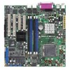
Motherboard layouts P5MT model PS/2KBMS KBPWR1 T: Mouse PSUSMB1 B: Keyboard USBPW12 USB12 REAR_FAN1 25cm (9.8in) ATXPWR1 ATX12V1 CPU_FAN1 COM1 REAR_FAN2 CPU_FAN2 FM_CPU2 Intel E7230 FM_CPU1 LGA775 PARALLEL PORT ® P5MT Super I/O SB_PWR1 8Mbit Flash BIOS RECOVERY1 PCI4 BPSMB1 TRPWR1 - Asus P5MT-M | User Guide - Page 24
(9.8in) ATXPWR1 ATX12V1 CPU_FAN1 COM1 REAR_FAN2 CPU_FAN2 FM_CPU2 Intel E7230 FM_CPU1 LGA775 PARALLEL PORT ® P5MT/SCSI VGA1 LAN1 DDR2 DIMM_A1 (64 bit,240-pin RAGE XL VGA Controller Super I/O SB_PWR1 8Mbit Flash BIOS RECOVERY1 PCI4 BPSMB1 TRPWR1 AUX_PANEL1 BMCCONN1 HDLED1 LSI 1020A - Asus P5MT-M | User Guide - Page 25
/PCI-X/PCI Express slots 4. Zero-Channel RAID socket Jumpers 1. Clear RTC RAM (CLRTC1) 2. CPU fan pin selection (3-pin FM_CPU1, FM_CPU2) RAID controller selection (3-pin RAID_SEL1) 8. SCSI controller setting (3-pin SCSI_EN1) (P5MT/SCSI model only) 9. Force BIOS 23 2-23 2-23 2-23 ASUS P5MT Series 2-5 - Asus P5MT-M | User Guide - Page 26
pin USB34) 6. Ultra320 SCSI connectors (one 68-pin SCSIA1) (present in P5MT/SCSI model only) 7. Serial port connector (10-1 pin COM2) 8. BMC connector 16-pin BMCCONN1) 9. Ambient thermal sensor (2-pin TRPWR1) 10. CPU and system fan connectors (3-pin CPU_FAN1/2, REAR_FAN1/2, FRNT_FAN1/2) 11. - Asus P5MT-M | User Guide - Page 27
LGA775 socket. • The product warranty does not cover damage to the socket contacts resulting from incorrect CPU installation/removal, or misplacement/loss/incorrect removal of the PnP cap. 2.3.1 Installing the CPU To install a CPU: 1. Locate the CPU socket on the motherboard. LAN2 P5MT Series CPU - Asus P5MT-M | User Guide - Page 28
socket pins, do not remove the PnP cap unless you are installing a CPU. 3. Lift the load lever in the direction of the arrow to PnP cap from the load plate window to remove (B). B A Load plate 5. Position the CPU over the socket, making sure that the gold triangle is on the bottom-left corner of - Asus P5MT-M | User Guide - Page 29
tab. B The motherboard supports Intel® Pentium® 4 LGA775 processors with the Intel® Enhanced Memory 64 Technology (EM64T), Enhanced Intel SpeedStep® Technology (EIST), and Hyper-Threading Technology. Refer to the Appendix for more information on these CPU features. ASUS P5MT Series 2-9 - Asus P5MT-M | User Guide - Page 30
the heatsink and fan assembly. Make sure that you have installed the motherboard to the chassis before you install the CPU fan and heatsink assembly. To install the CPU heatsink and fan: 1. Place the heatsink on top of the installed CPU, making sure that the four fasteners match the holes on the - Asus P5MT-M | User Guide - Page 31
on the motherboard labeled CPU_FAN. CPU_FAN1 CPU_FAN1 ® GND FANPWR2 FANOUT4 LAN2 CPU_FAN2 CPU_FAN2 FANOUT4 FANPWR2 GND P5MT Series CPU fan connectors Do not forget to connect the CPU fan connector! Hardware monitoring errors can occur if you fail to plug this connector. ASUS P5MT Series - Asus P5MT-M | User Guide - Page 32
2.3.3 Uninstalling the CPU heatsink and fan To uninstall the CPU heatsink and fan: 1. Disconnect the CPU fan cable from the connector on the motherboard. 2. Rotate each fastener counterclockwise. 3. Pull up two fasteners at a time in a diagonal sequence to disengage the heatsink and fan B - Asus P5MT-M | User Guide - Page 33
2.4 System memory 2.4.1 Overview The motherboard comes with four Double Data Rate II (DDR2) Dual Inline Memory Modules (DIMM) sockets to support 240-pin DDR modules. The figure illustrates the location of the DDR DIMM sockets: ® 128 Pins 112 Pins LAN2 DIMM_A1 DIMM_A2 P5MT Series 240-pin DDR2 - Asus P5MT-M | User Guide - Page 34
components. Failure to do so may cause severe damage to both the motherboard and the components. To install a DIMM: 1. Unlock a DIMM socket into a socket to avoid damaging the DIMM. • The DDR2 DIMM sockets do not support DDR DIMMs. DO NOT install DDR DIMMs to the DDR2 DIMM sockets. 2.4.4 Removing - Asus P5MT-M | User Guide - Page 35
your motherboard drivers for the expansion card. When using PCI cards on shared slots, ensure that the drivers support "Share IRQ" or that the cards do not need IRQ assignments. Otherwise, conflicts will arise between the two PCI groups, making the system unstable and the card inoperable. ASUS P5MT - Asus P5MT-M | User Guide - Page 36
Channel * These IRQs are usually available for ISA or PCI devices. PCI Bus Number, IDSEL, and IRQ assignments Description PATA Controller SATA Controller SMBus Controller USB1 UHCI Controller #1 USB1 UHCI Controller #2 USB 2.0 EHCI Controller BMC5721 #1 BMC5721 #2 ATI RAGE XL LSI 53C1020A (SCSI - Asus P5MT-M | User Guide - Page 37
optional ZCR card, install the card on PCI_X2 slot (colored green on P5MT/SCSI model). 2.5.5 PCI Express x16 slot This motherboard supports PCI Express x16 I/O, and graphic cards that comply with the PCI Express specifications. The following figure shows a graphics card installed on the PCI Express - Asus P5MT-M | User Guide - Page 38
the Real Time Clock (RTC) RAM in CMOS. You can clear the CMOS memory of date, time, and system setup parameters by erasing the CMOS RTC RAM data the computer. 6. Hold down the key during the boot process and enter BIOS setup to re-enter data. Except when clearing the RTC RAM, never remove the - Asus P5MT-M | User Guide - Page 39
to wake up the computer from S1 sleep mode (CPU stopped, DRAM refreshed, system running in low power Service Pack 4 to wake up the system from S4 sleep mode. • The total current consumed must NOT exceed the power supply capability (+5VSB) whether under normal condition or in sleep mode. ASUS P5MT - Asus P5MT-M | User Guide - Page 40
requires an ATX power supply that can supply at least 1A on the +5VSB lead, and a corresponding setting in the BIOS. KBPWR1 12 23 ® +5V +5VSB LAN2 (Default) P5MT Series Keyboard power setting 5 . VGA controller setting (3-pin VGA_EN1) These jumpers allow you to enable or disable the onboard - Asus P5MT-M | User Guide - Page 41
over pins 1-2 if you want to use the LSI Logic Embedded SATA RAID Setup Utility (default); otherwise, place the jumper caps to pins 2-3 to use the Intel® Matrix Storage Manager. LAN2 RAID_SEL1 1 2 LSI RAID ROM (Default) 2 3 INTEL RAID ROM P5MT Series RAID_SEL1 setting ASUS P5MT Series 2-21 - Asus P5MT-M | User Guide - Page 42
53C1020A PCI-X SCSI controller. Set to pins 1-2 to activate the SCSI feature, and support RAID configurations. ® ® LAN2 SCSI_EN1 12 23 Enable (Default) P5MT Series SCSI_EN1 setting Disable 9 . Force BIOS recovery setting (3-pin RECOVERY1) This jumper allows you to quickly update or recover - Asus P5MT-M | User Guide - Page 43
BLINKING No link Linked Data activity OFF ORANGE GREEN 10 Mbps connection 100 Mbps connection 1000 Mbps connection ACT/LINK SPEED LED LED LAN port ASUS P5MT Series 2-23 - Asus P5MT-M | User Guide - Page 44
NOTE: Orient the red markings on the floppy ribbon cable to PIN 1. P5MT Series Floppy disk drive connector 2 . Primary IDE connector (40-1 pin PRI_IDE1) three connectors: a blue connector for the primary IDE connector on the motherboard, a black connector for an Ultra ATA 100/66/33 IDE slave device - Asus P5MT-M | User Guide - Page 45
RSATA_RXN3 GND P5MT Series SATA connectors GND RSATA_TXP1 RSATA_TXN1 GND RSATA_RXP1 RSATA_RXN1 GND Important notes on Serial ATA • You must install Windows® 2000 Service Pack 4 or Windows® 2003 before using Serial ATA hard disk drives. The Serial ATA RAID feature (RAID 0/RAID 1) is available - Asus P5MT-M | User Guide - Page 46
to the SCSI connectors or the SATA connectors cause this LED to light up. HDLED1 1 LAN2 P5MT Series SCSI/SATA card activity LED connector 5. USB This USB connector complies with USB 2.0 specification that supports up to 480 Mbps connection speed. LAN2 USB34 P5MT Series USB 2.0 connector The USB port - Asus P5MT-M | User Guide - Page 47
SCSIA1) (P5MT/SCSI model only) This motherboard comes with the LSI53C1020A PCI-X SCSI U320 controller that supports one 68-Pin Ultra320 SCSI connector. The SCSI channel can support a maximum of 15 SCSI devices on a single channel decreases performance of the slower device. ASUS P5MT Series 2-27 - Asus P5MT-M | User Guide - Page 48
back of the system chassis. The serial port module is purchased separately. COM2 LAN2 PIN 1 P5MT Series Serial port2 (COM2) connector 8. BMC connector (16-pin BMCCONN1) This connector is for the ASUS server management card, if available. +5VSB +5VSB BMC SMBCLK 12CCLK1 PSON# BMC_RST# PWROK PSONEN - Asus P5MT-M | User Guide - Page 49
10. CPU and system fan connectors (3-pin CPU_FAN1/2, REAR_FAN1/2, FRNT_FAN1/2) The fan connectors support cooling fans of 350 mA ~ 740 mA (8.88 W max.) or a total of 2.1 A ~ 4.44 A (53.28 W max.) at +12V. Connect the fan cables to the fan connectors on the motherboard, making sure that the black - Asus P5MT-M | User Guide - Page 50
SMB cable, if your power supply supports the SMBus function. ® PSU_I2CCLK PSU_I2CDATA NC GND +3.3V Remote Sense LAN2 PSUSMB1 P5MT Series Power supply SMBus connector 1 3 connectors completely fit. • Use of an SSI 12 V Specification 2.0-compliant power supply unit (PSU) that provides a minimum - Asus P5MT-M | User Guide - Page 51
pin PANEL1) This connector supports several chassis-mounted functions. puts the system in sleep or soft-off mode depending on the BIOS settings. Pressing the power switch for more than four seconds while the RESETBTN# GND LAN2 PANEL1 P5MT Series System panel connector The system panel connector is - Asus P5MT-M | User Guide - Page 52
are for the locator switch and LED on the front panel. Front panel SMB LAN activity LED LAN2 AUX_PANEL1 PIN1 P5MT Series Auxiliary panel connector Chassis Locator LED intrusion and switch NC I2C_4_CLK# GND I2C_4_DATA# +5VSB LAN1_LINKACTLED+ LAN1_LINKACTLEDLAN2_LINKACTLEDLAN2_LINKACTLED+ ® +5VSB - Asus P5MT-M | User Guide - Page 53
This chapter describes the power up Powerin3g up sequence, and ways of shutting down the system. - Asus P5MT-M | User Guide - Page 54
Chapter summary 3 3.1 Starting up for the first time 3-1 3.2 Powering off the computer 3-2 ASUS P5MT Series - Asus P5MT-M | User Guide - Page 55
then runs the power-on self tests or POST. While the tests are running, the BIOS beeps (see BIOS beep codes table below) or additional messages appear on the screen. If you do not see on, hold down the key to enter the BIOS Setup. Follow the instructions in Chapter 4. ASUS P5MT Series 3-1 - Asus P5MT-M | User Guide - Page 56
is ON, pressing the power switch for less than four seconds puts the system to sleep mode or to soft-off mode, depending on the BIOS setting. Pressing the power switch for more than four seconds lets the system enter the soft-off mode regardless of the - Asus P5MT-M | User Guide - Page 57
This chapter tells how to change the system settings through the BIOS Setup menus. Detailed descriptions of the BIOS parameters are also provided. 4 BIOS setup - Asus P5MT-M | User Guide - Page 58
Chapter summary 4 4.1 Managing and updating your BIOS 4-1 4.2 BIOS setup program 4-10 4.3 Main menu 4-13 4.4 Advanced menu 4-18 4.5 Power menu 4-28 4.6 Boot menu 4-33 4.7 Exit menu 4-38 ASUS P5MT Series - Asus P5MT-M | User Guide - Page 59
BIOS using a bootable floppy disk or the motherboard support CD when the BIOS file fails or gets corrupted.) 3. A S U S U p d a t e (Updates the BIOS options field, then click S t a r t. 2. Copy the original or the latest motherboard BIOS file to the bootable floppy disk. ASUS P5MT Series 4-1 - Asus P5MT-M | User Guide - Page 60
actual BIOS screen displays may not be the same as shown. 1. Copy the AFUDOS utility (afudos.exe) from the motherboard support CD to the bootable floppy disk you created earlier. 2. Boot the system in DOS mode, then at the prompt type: afudos /o[filename] where the [filename] is any user-assigned - Asus P5MT-M | User Guide - Page 61
(www.asus.com) and download the latest BIOS file for the motherboard. Save the BIOS file to a bootable floppy disk. Write the BIOS filename on a piece of paper. You need to type the exact BIOS filename at the DOS prompt. 2. Copy the AFUDOS utility (afudos.exe) from the motherboard support CD to - Asus P5MT-M | User Guide - Page 62
drive. A:\>afudos /iP5MT.ROM AMI Firmware Update Utility - Version 1.19(ASUS V2.07(03.11.24BB)) Copyright (C) 2002 American Megatrends, Inc. All rights reserved. WARNING!! Do not turn off power during flash BIOS Reading file ....... done Reading flash ...... done Advance Check ...... Erasing flash - Asus P5MT-M | User Guide - Page 63
2 utility The ASUS CrashFree BIOS 2 is an auto recovery tool that allows you to restore the BIOS file when it fails or gets corrupted during the updating process. You can update a corrupted BIOS file using the motherboard support CD or the floppy disk that contains the updated BIOS file. • Prepare - Asus P5MT-M | User Guide - Page 64
the BIOS! Doing so can cause system boot failure! 4. Restart the system after the utility completes the updating process. The recovered BIOS may not be the latest BIOS version for this motherboard. Visit the ASUS website (www.asus.com) to download the latest BIOS file. 4-6 Chapter 4: BIOS setup - Asus P5MT-M | User Guide - Page 65
, and • View the BIOS version information. This utility is available in the support CD that comes with the motherboard package. ASUS Update requires an Internet connection either through a network or an Internet Service Provider (ISP). Installing ASUS Update To install ASUS Update: 1. Place the - Asus P5MT-M | User Guide - Page 66
the Internet To update the BIOS through the Internet: 1. Launch the ASUS Update utility from the Windows® desktop by clicking S t a r t > P r o g r a m s > A S U S > A S U S U p d a t e > A S U S U p d a t e. The ASUS Update main window appears. 2. Select U p d a t e B I O S f r o m 3. Select - Asus P5MT-M | User Guide - Page 67
t e. The ASUS Update main window appears. 2. Select U p d a t e B I O S f r o m a f i l e option from the drop-down menu, then click N e x t. 3. Locate the BIOS file from the O p e n window, then click S a v e. 4. Follow the screen instructions to complete the update process. ASUS P5MT Series 4-9 - Asus P5MT-M | User Guide - Page 68
program This motherboard supports a programmable firmware chip that you can update using the provided utility described in section "4.1 Managing and updating your BIOS." Use the BIOS Setup program when you are installing a motherboard, reconfiguring your system, or prompted to "Run Setup". This - Asus P5MT-M | User Guide - Page 69
items Menu bar Configuration fields Main Advanced System Time System Date Legacy Diskette A Power IDE Configuration System Information BIOS SETUP UTILITY Boot Exit [11:10:19] [Thu 06/17/2005] [1.44M, 3.5 in] General the navigation keys differ from one screen to another. ASUS P5MT Series 4-11 - Asus P5MT-M | User Guide - Page 70
specific items for that menu. For example, selecting M a i n shows the Main menu items. The other items (Advanced, Power, Boot, and Exit) on the menu bar have their respective menu items. Main Advanced BIOS cannot select an item that is not user-configurable. A configurable field is enclosed in - Asus P5MT-M | User Guide - Page 71
navigate through them. Main Advanced System Time System Date Legacy Diskette A Power IDE Configuration System Information BIOS SETUP UTILITY Boot Exit [11:10:19] [Thu 06/17/2005] [1.44M, 3.5 in] in.] [1.2M , 5.25 in.] [720K , 3.5 in.] [1.44M, 3.5 in.] [2.88M, 3.5 in.] ASUS P5MT Series 4-13 - Asus P5MT-M | User Guide - Page 72
using the LSI Logic Embedded SATA RAID Setup Utility. The AHCI allows the onboard storage driver to enable advanced Serial ATA features that increases storage performance on random workloads by allowing the drive to internally optimize the order of commands. 4-14 Chapter 4: BIOS setup - Asus P5MT-M | User Guide - Page 73
support/chipsets/imst/sb/CS-012304.htm www.intel.com/support/chipsets/imst/sb/CS-012305.htm The SATA controller is set to Native mode when this item is set to [RAID] or [AHCI]. Legacy IDE Channels [SATA -2004, American Megatrends, Inc. The BIOS automatically detects the values opposite the dimmed - Asus P5MT-M | User Guide - Page 74
the appropriate IDE device type. Select [CDROM] if you are specifically configuring a CD-ROM drive. Select [ARMD] (ATAPI Removable Media mode. Setting to [Auto] enables the LBA mode if the device supports this mode, and if the device was not previously formatted with LBA 4-16 Chapter 4: BIOS setup - Asus P5MT-M | User Guide - Page 75
F1 General Help F10 Save and Exit ESC Exit v02.58 (C)Copyright 1985-2004, American Megatrends, Inc. AMI BIOS Displays the auto-detected BIOS information. Processor Displays the auto-detected CPU specification. System Memory Displays the auto-detected total system memory. ASUS P5MT Series 4-17 - Asus P5MT-M | User Guide - Page 76
of the Advanced menu items. Incorrect field values can cause the system to malfunction. Advanced BIOS SETUP UTILITY MPS Configuration Remote Access Configuration CPU Configuration Chipset Onboard Devices Configuration PCI/PnP Configure the MultiProcessor Table. Select Screen Select Item - Asus P5MT-M | User Guide - Page 77
Remote Access [Disabled] Serial port number Base Address, IRQ Serial Port Mode Flow Control Redirection After BIOS POST Terminal Type VT-UTFB Combo Key Support Sredir Memory Display Delay [COM1] [3F8h, 4] [115200 8,n,1] [None] [Always] [ANSI] [Disabled] [No Delay] Select Remote Access type - Asus P5MT-M | User Guide - Page 78
only adjust the R a t i o C M O S if you installed an unlocked CPU. Refer to the CPU documentation for details. Max CPUID Value Limit [Disabled] Setting this item to [Enabled] allows legacy operating systems to boot even without support for CPUs with extended CPUID functions. Configuration options - Asus P5MT-M | User Guide - Page 79
an Intel® Pentium® 4 CPU that supports the Hyper-Threading Technology. Hyper-Threading is not supported when you installed a dual-core CPU. Hyper-Threading Technology [Enabled details on how to use the EIST feature. • The motherboard comes with a BIOS file that supports EIST. ASUS P5MT Series 4-21 - Asus P5MT-M | User Guide - Page 80
menu allows you to change the advanced chipset settings. Select an item then press to display the sub-menu. Advanced BIOS SETUP UTILITY Advanced Chipset Settings WARNING: Setting wrong values in below sections may cause system to malfunction. North Bridge Configuration South Bridge - Asus P5MT-M | User Guide - Page 81
settings. Advanced BIOS SETUP UTILITY North Bridge Chipset Configuration Memory Remap Feature [Enabled the DRAM SPD (Serial Presence Detect). When disabled, you can manually set the DRAM timing parameters through the DRAM sub-items. The [5 DRAM Clocks] [6 DRAM Clocks] ASUS P5MT Series 4-23 - Asus P5MT-M | User Guide - Page 82
to change the Southbridge related settings. Advanced BIOS SETUP UTILITY South Bridge Chipset Configuration USB Functions , American Megatrends, Inc. USB Function [4 USB Ports] Allows you to enable a specific number of USB ports, or disable the USB function. Configuration options: [Disabled] [2 - Asus P5MT-M | User Guide - Page 83
Configuration menu allows you to change the Intel PCI Express controller related settings. Advanced BIOS SETUP UTILITY Configure advanced settings for PCI-X Hub I/O Port Decode VGA 16-Bit the decode for the VGA controller. Configuration options: [Disabled] [Enabled] ASUS P5MT Series 4-25 - Asus P5MT-M | User Guide - Page 84
Port2 Address Serial Port2 Mode Parallel Port Address Parallel Port Mode Parallel Port IRQ [Enabled] [3F8/IRQ4] [2F8/IRQ3] [Normal] [378] [Normal] [IRQ7] Allows BIOS to Enable or Disable Floppy Controller Select Screen Select Item +- Change Option F1 General Help F10 Save and Exit ESC Exit v02.58 - Asus P5MT-M | User Guide - Page 85
setting the memory size /PnP Settings BIOS SETUP UTILITY PCI Device] NO: Lets the BIOS configure all the devices int he When set to [No], BIOS configures all the devices BIOS assigns an IRQ to PCI VGA card if the card requests for an IRQ. When set to [No], BIOS PCI Device], the specific IRQ is free - Asus P5MT-M | User Guide - Page 86
Support [Enabled] Allows you to enable or disable the Advanced Configuration and Power Interface (ACPI) support in the Application-Specific Power On By PS/2 Keyboard Power On By PS/2 Mouse BIOS SETUP UTILITY [Enabled] [Suspend] [Suspend] [Disabled] [ motherboard Advance Power Management (APM) feature - Asus P5MT-M | User Guide - Page 87
[On/Off] Allows the system to go into On/Off mode or suspend mode when the power button is pressed. Configuration options: [On/Off] [Suspend] ASUS P5MT Series 4-29 - Asus P5MT-M | User Guide - Page 88
] System Time To set the alarm hour, highlight this item and press the or key to make the selection. Configuration options: [00] [1]... ~ [23] 4-30 Chapter 4: BIOS setup - Asus P5MT-M | User Guide - Page 89
Allows you to use specific keys on the keyboard to CPU Fan1 Speed CPU Fan2 Speed Front Fan1 Speed Front Fan2 Speed Rear Fan1 Speed Rear Fan2 Speed Power BIOS SETUP hardware monitor automatically detects and displays the motherboard and CPU temperatures. Select [Disabled] if you do - Asus P5MT-M | User Guide - Page 90
the motherboard, the field shows N/A. Smart Fan Control [Enabled] Allows you to enable or disable the ASUS Q- o l feature. CPU1 Temperature [XXX] MB Temperature [XXX] Displays the detected CPU and system threshold temperatures when the Smart Fan Control feature is enabled. VCORE1 Voltage, BIOS setup - Asus P5MT-M | User Guide - Page 91
Boot Device Priority 1st Boot Device 2nd Boot Device 3rd Boot Device 4th Boot Device 5th Boot Device BIOS SETUP UTILITY Boot [ATAPI CD-ROM] [1st FLOPPY DRIVE] [Hard Drive] [Network: MBA v7.7.5] ] [Network: MBA v7.7.5 Slot 0400] [Network: MBA v7.7.5 Slot 0300] [Disabled] ASUS NCLV-D2 Series 4-33 - Asus P5MT-M | User Guide - Page 92
Support Wait For 'F1' If Error Hit 'DEL' Message Display Interrupt 19 Capture [Enabled] [Enabled] [On] [Auto] [Enabled] [Enabled] [Enabled] Specifies the boot llows BIOS [Disabled] [Enabled] Set this item to [Enabled] to use the ASUS MyLogo2™ feature. Bootup Num-Lock [On] Allows you to select the - Asus P5MT-M | User Guide - Page 93
BIOS SETUP UTILITY Boot Supervisor Password : Not Installed User Password : Not Installed Change Supervisor Password Change User same steps as in setting a user password. To clear the supervisor "Password Uninstalled" appears. If you forget your BIOS password, you can clear it by erasing the - Asus P5MT-M | User Guide - Page 94
appear to allow you to change other security settings. BIOS SETUP UTILITY Boot Security Settings Supervisor Password : Installed User Password : Not Installed Change Supervisor Password User Access Level Change User Password Clear User Password Password Check [Full Access] [Setup] to - Asus P5MT-M | User Guide - Page 95
to clear the user password. Password Check [Setup] When set to [Setup], BIOS checks for user password when accessing the Setup utility. When set to [Always], BIOS checks for user password both when accessing Setup and booting the system. Configuration options: [Setup] [Always] ASUS NCLV-D2 Series - Asus P5MT-M | User Guide - Page 96
The Exit menu items allow you to load the optimal or failsafe default values for the BIOS items, and save or discard your changes to the BIOS items. Main Advanced Exit Options BIOS SETUP UTILITY Security Boot Exit Exit & Save Changes Exit & Discard Changes Discard Changes Load Setup Defaults - Asus P5MT-M | User Guide - Page 97
press to load the default settings. If you wish to cancel the command, select [Cancel] then press to return to the Exit menu. ASUS NCLV-D2 Series 4-39 - Asus P5MT-M | User Guide - Page 98
4-40 Chapter 4: BIOS setup - Asus P5MT-M | User Guide - Page 99
This chapter provides instructions for setting up, creating, and configuring RAID sets using the available utilities. 5RAID configuration - Asus P5MT-M | User Guide - Page 100
Chapter summary 5 5.1 Setting up RAID 5-1 5.2 LSI Logic Embedded SATA RAID Setup Utility 5-4 5.3 Global Array Manager 5-30 5.4 LSI Logic Configuration Utility 5-31 ASUS P5MT Series - Asus P5MT-M | User Guide - Page 101
up RAID The motherboard comes with the following RAID solutions: P5MT model • LSI Logic Embedded SATA RAID technology embedded in the Intel® ICH7R Southbridge supports up to two SATA hard disk drives and RAID 0, RAID 1, and RAID 10 configurations. P5MT/SCSI model • LSI Logic Embedded SATA RAID - Asus P5MT-M | User Guide - Page 102
the SATA hard disks for RAID configuration: 1. Install the SATA hard disks into the drive bays following the instructions in the system user guide. 2. Connect a SATA signal cable to the signal connector at the back of each drive and to the SATA connector on the motherboard. 3. Connect a SATA power - Asus P5MT-M | User Guide - Page 103
g i c C o n f i g u r a t i o n U t i l i t y if you installed SCSI hard disk drives to the SCSI connector(s) supported by the LSI53C1020A PCI-X SCSI controller (P5MT/SCSI model only). Refer to the succeeding sections for details on how to use each RAID configuration utility. ASUS P5MT Series 5-3 - Asus P5MT-M | User Guide - Page 104
Embedded SATA RAID Setup Utility The LSI Logic Embedded SATA RAID Setup Utility allows you to create RAID 0, RAID 1, or RAID 10 set(s) from SATA hard disk drives connected to the SATA connectors supported by the motherboard ICH7R Southbridge chip. To enter the LSI Logic Embedded SATA RAID Setup - Asus P5MT-M | User Guide - Page 105
stripe size (RAID 1 only). Using Easy Configuration To create a RAID set using the E a s y C o n f i g u r a t i o n option: 1. From the utility main menu, highlight C o n f i g u r e, then press . 2. Use the arrow keys to select Easy Configuration, then press . ASUS P5MT Series 5-5 - Asus P5MT-M | User Guide - Page 106
3. The A R R A Y S E L E C T I O N M E N U displays the available drives connected to the SATA ports. Select the drives you want to include in the RAID set, then press . When selected, the drive indicator changes from R E A D Y to ONLIN A[X]-[Y], where X is the array number, and Y is the - Asus P5MT-M | User Guide - Page 107
5. Press , select the configurable array, then press . The logical drive information appears including a Logical Drive menu that allows you to change the logical drive parameters. ASUS P5MT Series 5-7 - Asus P5MT-M | User Guide - Page 108
then press . You need at least two identical hard disk drives when creating a RAID 1 set. 8. When creating a RAID 1 set, select S t r i p e S i z e from the L o g i c a l D r i v e menu, then press . When creating a RAID 0 set, proceed to step 10. 9. Key-in the stripe size, then press - Asus P5MT-M | User Guide - Page 109
>. 12. Follow steps 5 to 10 to configure additional logical drives. 13. When prompted, save the configuration, then press to return to the Management Menu. ASUS P5MT Series 5-9 - Asus P5MT-M | User Guide - Page 110
data. If you do not want to delete the existing RAID set, use the V i e w / A d d C o n f i g u r a t i o n command to view or create another RAID configuration. To create a RAID set using the N e w C o n f i g u r a t i o n option: 1. From the utility main menu, highlight C o n f i g u r e, then - Asus P5MT-M | User Guide - Page 111
want to include in the RAID set, then press . When selected, the drive indicator changes from R E A D Y to ONLIN A[X]-[Y], where X is the array number, and Y is the drive number. The information of the selected hard disk drive displays at the bottom of the screen. ASUS P5MT Series 5-11 - Asus P5MT-M | User Guide - Page 112
4. Select all the drives required for the RAID 10 set, then press . The configurable array appears on screen. 5. Press , select the configurable array appears including a Logical Drive menu that allows you to change the logical drive parameters. 5-12 Chapter 5: RAID configuration - Asus P5MT-M | User Guide - Page 113
10 from the menu, then press . You need at least four identical hard disk drives when creating a RAID 10 set. 8. Select S t r i p e S i z e from the L o g i c a l D r i v e menu, then press . 9. , we recommend a higher array block size for optimum performance. ASUS P5MT Series 5-13 - Asus P5MT-M | User Guide - Page 114
10. When finished setting the selected logical drive configuration, select A c c e p t from the menu, then press . 11. When prompted, save the configuration, then press to return to the Management Menu. 5-14 Chapter 5: RAID configuration - Asus P5MT-M | User Guide - Page 115
want to include in the RAID set, then press . When selected, the drive indicator changes from R E A D Y to ONLIN A[X]-[Y], where X is the array number, and Y is the drive number. The information of the selected hard disk drive displays at the bottom of the screen. ASUS P5MT Series 5-15 - Asus P5MT-M | User Guide - Page 116
4. Select all the drives required for the RAID set, then press . The configurable array appears on screen. 5. Press , select the configurable array, then appears including a Logical Drive menu that allows you to change the logical drive parameters. 5-16 Chapter 5: RAID configuration - Asus P5MT-M | User Guide - Page 117
L o g i c a l D r i v e menu, then press . 8. Key-in the desired logical drive size, then press . 9. Follow steps 8 to 13 of the C r e a t i n g a R A I D s e t : U s i n g E a s y C o n f i g u r a t i o n section to add the new RAID configuration. ASUS P5MT Series 5-17 - Asus P5MT-M | User Guide - Page 118
the logical drive using the I n i t i a l i z e command: 1. From the Management Menu, highlight I n i t i a l i z e, then press . 2. The screen displays the available RAID set(s) and prompts you to select the logical drive to initialize. Use the arrow keys to select the logical drive from the - Asus P5MT-M | User Guide - Page 119
the drive without confirmation. Initializing a logical drive(s) erases all data on the drive. 4. A progress bar appears on screen. If desired, press to abort initialization. ASUS P5MT Series 5-19 - Asus P5MT-M | User Guide - Page 120
5. When initialization is completed, press . Using the Objects command To initialize the logical drives using the O b j e c t s command: 1. From the Management Menu, highlight O b j e c t s, then press . 5-20 Chapter 5: RAID configuration - Asus P5MT-M | User Guide - Page 121
the logical drive to initialize from the L o g i c a l D r i v e s sub-menu, then press . 4. Select Initialize from the pop-up menu, then press to start initialization. ASUS P5MT Series 5-21 - Asus P5MT-M | User Guide - Page 122
initialize the drive without confirmation. 6. A progress bar appears on screen. If desired, press to abort initialization. 7. When initialization is completed, press . 5-22 Chapter 5: RAID configuration - Asus P5MT-M | User Guide - Page 123
5.2.5 Rebuilding failed drives You can manually rebuild failed hard disk drives using the R e b u i l d command C A L D R I V E S S E L E C T I O N M E N U displays the available drives connected to the SATA ports. Select the drive you want to rebuild, then press . ASUS P5MT Series 5-23 - Asus P5MT-M | User Guide - Page 124
3. After selecting the drive to rebuild, press . The indicator for the selected drive now shows R B L D. 4. When prompted, press to to rebuild the drive. 5. When rebuild is complete, press any key to continue. 5-24 Chapter 5: RAID configuration - Asus P5MT-M | User Guide - Page 125
The Check Consistency command is available only for logical drives included in a RAID 1 set. Using the Check Consistency To check data consistency using the C e n c y, then press . 2. The screen displays the available RAID set(s) and prompts you to select the logical drive to check. Use the - Asus P5MT-M | User Guide - Page 126
. • Abort - Aborts the consistency check. When you restart checking, it continues from zero percent. 5. When checking is complete, press any key to continue. 5-26 Chapter 5: RAID configuration - Asus P5MT-M | User Guide - Page 127
from the pop-up menu, then press . 4. When prompted, press to to check the drive. 5. When checking is complete, press any key to continue. ASUS P5MT Series 5-27 - Asus P5MT-M | User Guide - Page 128
configuration To delete a RAID configuration: 1. From the Management Menu, select C o n f i g u r e > C l e a r C o n f i g u r a t i o n, then press . 2. When prompted, press the to select Y e s from the C l e a r C o n f i g u r a t i o n ? dialog box, then press . The - Asus P5MT-M | User Guide - Page 129
A I D s e t : U s i n g N e w C o n f i g u r a t i o n section for details. To select the boot drive from a RAID set: 1. From the Management Menu, select C o n f i g u r e > S e l e c t B o o t D r i v e, then press . 2. as boot drive. Press any key to continue. ASUS P5MT Series 5-29 - Asus P5MT-M | User Guide - Page 130
5.2.9 Enabling the WriteCache You may enable the RAID controller's W r i t e C a c h RAID set(s) in Windows® operating environment using the Global Array Manager (GAM) application. The GAM application is available from the motherboard support CD. Refer to the GAM user guide in the motherboard support - Asus P5MT-M | User Guide - Page 131
RAID 1, and RAID-1E from SCSI hard disk drives connected to the SCSI connectors supported by the LSI53C1020A PCI-X SCSI controller. To enter the LSI Logic Configuration Utility: 1. Turn on the system after installing all the SATA . Refer to the next section for details. ASUS P5MT Series 5-31 - Asus P5MT-M | User Guide - Page 132
the adapter boot sequence. Property Adapter PCI Bus Dev/Func Boot Order Description Identifies the specific family of LSI Logic Host Adapters. Identifies the PCI Bus number assigned by the system BIOS to an adapter (range 0x00 - 0xFF, 0 - 255 decimal). Identifies the PCI Device/Function assigned - Asus P5MT-M | User Guide - Page 133
, then press or change the value. Pause When Boot Alert Displayed This option specifies whether to pause for user acknowledgement after displaying an alert message during boot. If you want the user to press any key after displaying the alert message, set this item to [Yes]. Set this item to - Asus P5MT-M | User Guide - Page 134
when using a monochrome monitor. Support Interrupt Allows you to prevent a hook on INT40, if required. Disable Integrated RAID Allows you to disable bus scan search for RAID member devices. This item also allows you to disable configuration of RAID arrays in the BIOS. Allows you - Asus P5MT-M | User Guide - Page 135
e r t i e s page allows you to configure the device and RAID properties. To access the adapter properties screen, select the adapter from the Boot the D e v i c e P r o p e r t i e s page or the R A I D P r o p e r t i e s page. Refer to the corresponding sections for details. ASUS P5MT Series 5-35 - Asus P5MT-M | User Guide - Page 136
whether to pause for user acknowledgement after displaying an alert message during boot. If you want the user to press any key after v i c e P r o p e r t i e s page. Allows you to view, create, delete, and/or configure RAID arrays. Press to display the R A I D P r o p e - Asus P5MT-M | User Guide - Page 137
Support Allows you to specify the removable media support option for an adapter. Select [None] to disable removable media support With Media Installed] to enable support for removable media regardless of all partitions, then reboot the system to clear memory. If not, the old partitioning data will be - Asus P5MT-M | User Guide - Page 138
are shared with another adapter(s). When you set this option to [Yes] the Fusion-MPT PCI SCSI BIOS avoids SCSI Bus resets as much as possible when two or more devices are shared with the other adapter this option, then press to load the default settings. 5-38 Chapter 5: RAID configuration - Asus P5MT-M | User Guide - Page 139
the device's Inquiry Data. Sync Rate Displays the maximum synchronous data transfer rate, in Mega Transfers per second. Data Width Displays the maximum data width in bits. Scan ID Specifies whether to to the system. • Disable scan on a bus with only a few attached devices. ASUS P5MT Series 5-39 - Asus P5MT-M | User Guide - Page 140
this option to [No] if you have problems with a device that responds to all LUNs SCSI Timeout This field indicates the maximum amount of time [0 to 9999 seconds BIOS does not use queue tags. This item specifies queue tag control to higher level device drivers. 5-40 Chapter 5: RAID configuration - Asus P5MT-M | User Guide - Page 141
RAID Properties The R A I D P r o p e r t i e s page allows you update and view individual devices connected to the disk array. You can select a minimum of two drives and a maximum of six drives. Select a maximum of five drives when you select a hot spare. Hot Spare Sets the ASUS P5MT Series 5-41 - Asus P5MT-M | User Guide - Page 142
with data that you want to retain. This drive will become the primary copy of the array. • Integrated Mirrored array - Select a minimum of two drives • RAID-1E - Select a minimum of four drives The A r r a y label on top of the screen changes to IM or 1E depending on the number of selected hard - Asus P5MT-M | User Guide - Page 143
2. After selecting the drives, press . 3. When prompted, select , then press to create the RAID 1 set. ASUS P5MT Series 5-43 - Asus P5MT-M | User Guide - Page 144
) set You can create a striped array using the LSI Logic Configuration Utility. To create a RAID 0 set: 1. From the R A I D P r o p e r t i e s screen, select the drives that you want to include in the RAID 0 set. The A r r a y label on top of the screen changes to IS (Integrated Striping). 2. After - Asus P5MT-M | User Guide - Page 145
of the RAID Properties screen. Refer to the table below for the description of the diagnostic codes. Code 1 2 3 4 5 6 7 8 9 10 11 12 13 Description Problem with reading disk serial number Disk does not support SMART Unused Disk does not support wide data, synchrounous mode, or queue tagging User - Asus P5MT-M | User Guide - Page 146
, then press . Select < R A I D P r o p e r t i e s > from the Adapter Properties screen, then press . A tabbed menu appears on the top panel of the RAID Properties screen. You can now delete, add/delete hot spare drives, and/or activate arrays using the tabbed menus. Press to - Asus P5MT-M | User Guide - Page 147
> to select < D e l e t e A r r a y >. 2. Use the arrow keys to select the array you want to delete, then press . 3. Press . 4. When prompted, select < S a v e c h a n g e s , t h e n e x i t t h i s m e n u >, then press . ASUS P5MT Series 5-47 - Asus P5MT-M | User Guide - Page 148
Adding or deleting a hot spare drive To add a hot spare drive assigned to a RAID set: 1. From the RAID Properties screen, press to select . 2. Use the arrow keys to select the drive you want to assign as spare. 3. Move - Asus P5MT-M | User Guide - Page 149
u >, then press . To delete a hot spare drive assigned to a RAID set: 1. From the RAID Properties screen, press to select . 2. Use on a physical adapter. The RAID Properties screen allows display of one menu allows you to instruct the RAID firmware to activate a - Asus P5MT-M | User Guide - Page 150
5-50 Chapter 5: RAID configuration - Asus P5MT-M | User Guide - Page 151
This chapter provides instructions for installing the necessary drivers for different system components. 6Driver installation - Asus P5MT-M | User Guide - Page 152
Chapter summary 6 6.1 RAID driver installation 6-1 6.2 LAN driver installation 6-11 6.3 VGA driver installation 6-13 6.4 Management applications and utilities installation 6-15 ASUS P5MT Series - Asus P5MT-M | User Guide - Page 153
screen instructions to create the driver disk. For systems with Red Hat® Enterprise versions that are not listed in the Makedisk menu, explore the support CD and copy the RAID driver disk from the following path: \ D r i v e r s \ C h i p s e t \ I C H \ L S I \ D r i v e r \ L i n u x. ASUS P5MT - Asus P5MT-M | User Guide - Page 154
w s® 2000/2003 Server OS installation To install the RAID controller driver when installing Windows® 2000/ 2003 Server OS: 1. S C S I o r R A I D d r i v e r . . ." appears at the bottom of the screen. 3. When prompted, press to specify an additional device. 6-2 Chapter 6: Driver installation - Asus P5MT-M | User Guide - Page 155
r t D r i v e r (P5MT/SCSI model only). 6. The Windows® 2000/2003 Setup loads the RAID controller drivers from the RAID driver disk. When prompted, press to continue installation. 7. Setup then proceeds with the OS installation. Follow screen instructions to continue. ASUS P5MT Series 6-3 - Asus P5MT-M | User Guide - Page 156
, then select P r o p e r t i e s. 6. Click the D r i v e r tab, then click the U p d a t e D r i v e r button. 7. The U p g r a d e D e v i c e D r i v e r W i z a r d window appears. Click N e x t. 8. Insert the RAID driver disk you created earlier to the floppy disk drive. 9. Select the option - Asus P5MT-M | User Guide - Page 157
r t D r i v e r items should appear. 4. Right-click the RAID controller driver item, then select P r o p e r t i e s from the menu. 5. Click the D r i v e r tab, then click the D r i v e r D e t a i l s button to display the RAID controller drivers. 6. Click O K when finished. ASUS P5MT Series 6-5 - Asus P5MT-M | User Guide - Page 158
Red Hat® Enterprise ver. 3.0 To install the Intel® ICH7R LSI Logic Embedded SATA RAID controller driver when installing Red Hat® Enterprise ver. 3.0 OS: 1. Boot the system from the Red Hat® Installation CD. 2. At the boot:, type linux dd , then press . 6-6 Chapter 6: Driver installation - Asus P5MT-M | User Guide - Page 159
3. Select Y e s using the key when asked if you have the driver disk. Press 4. Select f d 0 using the key when asked to select the driver disk source. Press to move the cursor to O K, then press . ASUS P5MT Series 6-7 - Asus P5MT-M | User Guide - Page 160
asked if you will load additional RAID controller drivers: • For P5MT model, select N o, then press • For P5MT/SCSI model, select Y e s, then install the additional RAID controller drivers (for LSI53C1020A PCI-X SCSI controller). 7. Follow screen instructions to continue the OS installation - Asus P5MT-M | User Guide - Page 161
Linux To install the RAID controller driver when installing SuSE Linux OS: 1. Boot the system from the SuSE Installation CD. 2. Select Installation from the B o o t O p t i o n s menu, then press . 3. A message instructs you to prepare the RAID driver disk. Press . ASUS P5MT Series 6-9 - Asus P5MT-M | User Guide - Page 162
, insert the RAID driver disk to the floppy disk drive, then press . 5. When prompted, select the floppy disk drive (fd0) as the driver update medium, select OK, then press . The drivers for the RAID controller are installed to the system. 6-10 Chapter 6: Driver installation - Asus P5MT-M | User Guide - Page 163
Windows® 2000/2003 Server To install the Broadcom® Gigabit LAN controller driver on a Windows® 2000/2003 Server OS: 1. Restart the computer, then log on with A d m i n i s t r a t o r privileges. 2. Insert the motherboard/system support CD to the optical drive. The CD automatically displays the - Asus P5MT-M | User Guide - Page 164
continue installation. 6.2.2 Red Hat® Enterprise ver. 3.0 Follow these instructions when installing the Broadcom® Gigabit LAN controller base driver for the Red Hat® Enterprise ver. 3.0 operating system. Building the driver from the TAR file Install first the K e r n e l D e v e l o p m e n t tools - Asus P5MT-M | User Guide - Page 165
® 2000 Server You need to manually install the ATI® RAGE XL VGA driver on a Windows® 2000 Server operating system. To install the ATI® RAGE XL VGA driver: 1. Restart the computer, then log on with A d m i n i s t r a t o r privileges. 2. Insert the motherboard/system support CD to the optical drive - Asus P5MT-M | User Guide - Page 166
2003 Server The Windows® 2003 Server operating system automatically recognizes the ATI® RAGE XL VGA driver during system installation. There is no need to install an additional driver(s) to support the onboard VGA. 6.3.3 Red Hat® Enterprise ver. 3.0 The Red Hat® Enterprise ver. 3.0 operating system - Asus P5MT-M | User Guide - Page 167
package contains the drivers, management applications, and utilities that you can install to avail all motherboard features. The contents of the support CD are subject to change at any time without notice. Visit the ASUS website (www.asus.com) for updates. 6.4.1 Running the support CD Place the - Asus P5MT-M | User Guide - Page 168
and utilities that the motherboard supports. Click on an item to install. 6.4.5 Contact information Click the C o n t a c t tab to display the ASUS contact information. You can also find this information on the inside front cover of this user guide. 6-16 Chapter 6: Driver installation - Asus P5MT-M | User Guide - Page 169
This appendix includes additional information that you may refer to when configuring the motherboard. Reference A information - Asus P5MT-M | User Guide - Page 170
Appendix summary A A.1 Intel® EM64T A-1 A.2 Enhanced Intel SpeedStep® Technology (EIST A-1 A.3 Intel® Hyper-Threading Technology A-3 A.4 Block diagrams A-4 ASUS P5MT Series - Asus P5MT-M | User Guide - Page 171
compatible with Intel® Pentium® 4 LGA775 processors running on 32-bit operating systems. • The motherboard comes with a BIOS file that supports EM64T. You can download the latest BIOS file from the ASUS website (www.asus.com/support/download/) if you need to update the BIOS file. See Chapter 4 for - Asus P5MT-M | User Guide - Page 172
A.2.2 Using the EIST To use the EIST feature: 1. Turn on the computer, then enter the BIOS Setup. 2. Go to the Advanced Menu, highlight CPU Configuration, then press . 3. Set the Intel(R) SpeedStep Technology item to [Automatic], then press . See page 4-21 for details. 4. Press - Asus P5MT-M | User Guide - Page 173
motherboard supports Intel® Pentium® 4 LGA775 processors with Hyper-Threading Technology. • Hyper-Threading Technology is supported See page 4-21 for details. The BIOS item appears only if you installed a CPU that supports Hyper-Threading Techonology. 3. Restart the computer. ASUS P5MT Series A-3 - Asus P5MT-M | User Guide - Page 174
A.4 Block diagrams A.4.1 P5MT model Intel¤ Pentium¤4 Processor in the 775-land package with 800/1066 MHz system bus System Bus 64bit, 800 MHz/1066MHz Northbridge Intel¤ E7230 Four DDR2 533/667 DIMM Sockets 4xDDR2 533/667 DIMM slots (max. 8 GB) X8 PCI-E PCIE Slot 1 PCI-E interfaces VGA-Conn. - Asus P5MT-M | User Guide - Page 175
Broadcom BCM5751 LAN Port 1 LAN Port 2 IDE SATA All USB 1-8 SMBus H/W monitor W83792AD Fan EEPROM System information Power Supply LPC-Bus W83627EHF-A PS2 KB/MS Floppy Serial Port Parallel Port BIOS Flash 8 Mbit PCI Slot 4 PCI-X Slot 2 PCI-X Slot 3 Mini PCI (BMC) ASUS P5MT Series A-5 - Asus P5MT-M | User Guide - Page 176
A-6 Appendix A: Reference information
-
 1
1 -
 2
2 -
 3
3 -
 4
4 -
 5
5 -
 6
6 -
 7
7 -
8
-
9
-
10
-
11
-
12
-
13
-
14
-
15
-
16
-
17
-
18
-
19
-
20
-
21
-
22
-
23
-
24
-
25
-
26
-
27
-
28
-
29
-
30
-
31
-
32
-
33
-
34
-
35
-
36
-
37
-
38
-
39
-
40
-
41
-
42
-
43
-
44
-
45
-
46
-
47
-
48
-
49
-
50
-
51
-
52
-
53
-
54
-
55
-
56
-
57
-
58
-
59
-
60
-
61
-
62
-
63
-
64
-
65
-
66
-
67
-
68
-
69
-
70
-
71
-
72
-
73
-
74
-
75
-
76
-
77
-
78
-
79
-
80
-
81
-
82
-
83
-
84
-
85
-
86
-
87
-
88
-
89
-
90
-
91
-
92
-
93
-
94
-
95
-
96
-
97
-
98
-
99
-
100
-
101
-
102
-
103
-
104
-
105
-
106
-
107
-
108
-
109
-
110
-
111
-
112
-
113
-
114
-
115
-
116
-
117
-
118
-
119
-
120
-
121
-
122
-
123
-
124
-
125
-
126
-
127
-
128
-
129
-
130
-
131
-
132
-
133
-
134
-
135
-
136
-
137
-
138
-
139
-
140
-
141
-
142
-
143
-
144
-
145
-
146
-
147
-
148
-
149
-
150
-
151
-
152
-
153
-
154
-
155
-
156
-
157
-
158
-
159
-
160
-
161
-
162
-
163
-
164
-
165
-
166
-
167
-
168
-
169
-
170
-
171
-
172
-
173
-
174
-
175
-
176
 |
 |

Motherboard
P5MT
Series
P5MT
P5MT
P5MT
P5MT
P5MT
P5MT/SCSI
P5MT/SCSI
P5MT/SCSI
P5MT/SCSI
P5MT/SCSI