Asus P5RD2-VM Motherboard Installation Guide
Asus P5RD2-VM Manual
 |
View all Asus P5RD2-VM manuals
Add to My Manuals
Save this manual to your list of manuals |
Asus P5RD2-VM manual content summary:
- Asus P5RD2-VM | Motherboard Installation Guide - Page 1
P5RD2-VM Motherboard - Asus P5RD2-VM | Motherboard Installation Guide - Page 2
"). Product warranty or service will not be extended if: (1) the product is repaired, modified or altered, unless such repair, modification of alteration is authorized in writing by ASUS; or (2) the serial number of the product is defaced or missing. ASUS PROVIDES THIS MANUAL "AS IS" WITHOUT WARRANTY - Asus P5RD2-VM | Motherboard Installation Guide - Page 3
vii About this guide viii Typography ix P5RD2-VM specifications summary x Chapter 1: Product introduction 1.1 Welcome 1-2 1.2 Package contents 1-2 1.3 Special features 1-2 1.3.1 Product highlights 1-2 1.3.2 Innovative ASUS features 1-4 1.4 Before you proceed 1-5 1.5 Motherboard overview - Asus P5RD2-VM | Motherboard Installation Guide - Page 4
utility 2-4 2.1.4 ASUS CrashFree BIOS 2 utility 2-6 2.1.5 ASUS Update utility 2-8 2.2 BIOS setup program 2-11 2.2.1 BIOS menu screen 2-12 2.2.2 Menu bar 2-12 2.2.3 Navigation keys 2-12 2.2.4 Menu items 2-13 2.2.5 Sub-menu items 2-13 2.2.6 Configuration fields 2-13 2.2.7 Pop-up window 2-13 - Asus P5RD2-VM | Motherboard Installation Guide - Page 5
36 Chapter 3: Software support 3.1 Installing an operating system 3-2 3.2 Support CD information 3-2 3.2.1 Running the support CD 3-2 3.2.2 Drivers menu 3-3 3.2.3 Utilities menu 3-4 3.2.4 Make Disk 3-5 3.2.5 Manual menu 3-6 3.2.6 ASUS Contact information 3-6 Appendix: CPU features A.1 Intel - Asus P5RD2-VM | Motherboard Installation Guide - Page 6
. This equipment generates, uses and can radiate radio frequency energy and, if not installed and used in accordance with manufacturerʼs instructions, may cause harmful interference to radio communications. However, there is no guarantee that interference will not occur in a particular installation - Asus P5RD2-VM | Motherboard Installation Guide - Page 7
service technician or your retailer. Operation safety • Before installing the motherboard and adding devices on it, carefully read all the manuals and staples away from connectors, slots, sockets and circuitry. • Avoid dust, technical problems with the product, contact a qualified service technician - Asus P5RD2-VM | Motherboard Installation Guide - Page 8
The Appendix describes the CPU features that the motherboard supports. Where to find more information Refer to the following sources for additional information and for product and software updates. 1. ASUS websites The ASUS website provides updated information on ASUS hardware and software products - Asus P5RD2-VM | Motherboard Installation Guide - Page 9
of the following symbols used throughout this manual. DANGER/WARNING: Information to prevent injury to yourself when trying to complete a task. CAUTION: Information to prevent damage to the components when trying to complete a task. IMPORTANT: Instructions that you MUST follow to complete a task - Asus P5RD2-VM | Motherboard Installation Guide - Page 10
P5RD2-VM specifications summary CPU Chipset Front Side Bus Memory VGA Expansion slots Storage Audio LAN USB Rear panel LGA775 socket for Intel® Pentium® D/Intel® Pentium® 4 or Intel® Celeron® processors Compatible with Intel® PCG 05B/05A processors Supports Enhanced Intel SpeedStep® Technology ( - Asus P5RD2-VM | Motherboard Installation Guide - Page 11
P5RD2-VM specifications summary BIOS features Special features Industry standard Manageability Internal connectors Power Requirement Form Factor Support CD contents 4 Mb Flash ROM, AMI BIOS, PnP, WfM2.0, DMI2.0, SM BIOS 2.3, ASUS EZ Flash ASUS EZ Flash ASUS CrashFree BIOS 2 ASUS MyLogo™ PCI 2.2, - Asus P5RD2-VM | Motherboard Installation Guide - Page 12
xii - Asus P5RD2-VM | Motherboard Installation Guide - Page 13
This chapter describes the motherboard features and the new technologies it supports. 1Product introduction ASUS P5RD2-VM 1-1 - Asus P5RD2-VM | Motherboard Installation Guide - Page 14
CDs ASUS motherboard support CD Documentation User guide If any of the above items is damaged or missing, contact your retailer. 1.3 Special features 1.3.1 Product highlights Latest processor technology The motherboard comes with a 775-pin surface mount Land Grid Array (LGA) socket designed - Asus P5RD2-VM | Motherboard Installation Guide - Page 15
high speed interface is software compatible with existing PCI specifications. See page 1-21 for details. 6-channel audio The motherboard comes with the ADI AD1986A audio CODEC that provides 6-channel audio, audio jack-sensing and enumeration technology, and S/PDIF out support. See page 1-25 and 1-26 - Asus P5RD2-VM | Motherboard Installation Guide - Page 16
MyLogo™ This new feature present in the motherboard allows you to personalize and add style to your system with customizable boot logos. See details on page 2-33. ASUS EZ Flash BIOS With the ASUS EZ Flash, you can easily update the system BIOS even before loading the operating system. No need to - Asus P5RD2-VM | Motherboard Installation Guide - Page 17
install motherboard components or change any motherboard settings. • Unplug the power cord from the wall socket before motherboard component. The illustration below shows the location of the onboard LED. P5RD2-VM ® P5RD2-VM Onboard LED SB_PWR ON Standby Power OFF Powered Off ASUS P5RD2-VM - Asus P5RD2-VM | Motherboard Installation Guide - Page 18
image below. 1.5.2 Screw holes Place eight (6) screws into the holes indicated by circles to secure the motherboard to the chassis. Do not overtighten the screws! Doing so can damage the motherboard. Place this side towards the rear of the chassis P5RD2-VM ® 1-6 Chapter 1: Product introduction - Asus P5RD2-VM | Motherboard Installation Guide - Page 19
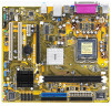
Super I/O FLOPPY PRI_IDE SEC_IDE 21.8cm (8.6in) 1.5.3 Motherboard layout PS/2KBMS T: Mouse B: Keyboard COM1 ATX12V KBPWR P5RD2-VM CR2032 3V Lithium Cell CMOS Power ® PCI1 ULI M1575 SATA4 SATA3 SATA2 SATA1 PCI2 USB56 USB78 CLRTC CHASSIS USBPW56 USBPW78 4M BIOS LPC PANEL ASUS P5RD2-VM - Asus P5RD2-VM | Motherboard Installation Guide - Page 20
/removal, or misplacement/ loss/incorrect removal of the PnP cap. 1.6.1 Installling the CPU To install a CPU: 1. Locate the CPU socket on the motherboard. P5RD2-VM ® P5RD2-VM CPU Socket 775 Before installing the CPU, make sure that the socket box is facing towards you and the load lever is on your - Asus P5RD2-VM | Motherboard Installation Guide - Page 21
the PnP cap B from the load plate window to remove (B). Load plate 5. Position the CPU over the socket, making sure that the gold triangle is on the bottom-left corner of the socket. The socket alignment key should fit Alignment key into the CPU notch. Gold triangle mark ASUS P5RD2-VM A 1-9 - Asus P5RD2-VM | Motherboard Installation Guide - Page 22
only one correct orientation. DO NOT force the CPU into the socket to prevent bending the connectors on the socket and damaging the CPU! The motherboard supports Intel® Pentium® D or Intel® Pentium® 4 LGA775 processors with the Intel® Enhanced Memory 64 Technology (EM64T), Enhanced Intel SpeedStep - Asus P5RD2-VM | Motherboard Installation Guide - Page 23
. To install the CPU heatsink and fan: 1. Place the heatsink on top of the installed CPU, making sure that the four fasteners match the holes on the motherboard. Fastener Motherboard hole Make sure each fastener is oriented as shown, with the narrow groove directed outward. ASUS P5RD2-VM 1-11 - Asus P5RD2-VM | Motherboard Installation Guide - Page 24
fan and heatsink assembly is in place, connect the CPU fan cable to the connector on the motherboard labeled CPU_FAN. P5RD2-VM ® CPU_FAN CPU FAN PWM CPU FAN IN CPU FAN PWR GND P5RD2-VM CPU Fan Connector Do not forget to connect the CPU fan connector! Hardware monitoring errors can occur if you - Asus P5RD2-VM | Motherboard Installation Guide - Page 25
and fan: 1. Disconnect the CPU fan cable from the connector on the motherboard. 2. Rotate each fastener counterclockwise. 3. Pull up two fasteners at a time in a diagonal sequence to disengage the heatsink B and fan assembly from the A A motherboard. B A B B A ASUS P5RD2-VM 1-13 - Asus P5RD2-VM | Motherboard Installation Guide - Page 26
4. Remove the heatsink and fan assembly from the motherboard. 5. Rotate each fastener clockwise to reset the orientation. The narrow end of the groove should point outward after resetting. (The photo shows the groove shaded - Asus P5RD2-VM | Motherboard Installation Guide - Page 27
compatibility, it is recommended that you obtain memory modules from the same vendor. Refer to the DDR2 Qualified Vendors List on the next page for details. • This motherboard does not support memory modules made up of 128 Mb chips or double sided x16 memory modules. DIMM1 DIMM2 ASUS P5RD2-VM - Asus P5RD2-VM | Motherboard Installation Guide - Page 28
Sockets DIMM2 (black) Populated Populated 1.7.3 DDR Qualified Vendors List The following table lists the memory modules that have been tested and qualified for use with this motherboard. Visit the ASUS website (www.asus -6E-E CL Brand Side(s) Component DIMM support A B N/A N/A SS KVR667D2N5/512 - Asus P5RD2-VM | Motherboard Installation Guide - Page 29
DDR2 533 Qualified Vendors List Size 256MB 512MB 1024MB Support: A : Supports one module inserted in any slot as Single-channel memory configuration B : Supports one pair of modules inserted into eithor the blue slots or the black slots as one pair of Dual-channel memory configuration ASUS P5RD2-VM - Asus P5RD2-VM | Motherboard Installation Guide - Page 30
before adding or removing DIMMs or other system components. Failure to do so can cause severe damage to both the motherboard and the components. 1. Unlock a DIMM socket by pressing the retaining clips outward. 2. Align a DIMM on the socket such that the notch on the DIMM matches the break on the - Asus P5RD2-VM | Motherboard Installation Guide - Page 31
cards that they support. Make sure unit cover (if your motherboard is already installed in a BIOS settings, if any. See Chapter 2 for information on BIOS setup. 2. Assign an IRQ to the card. Refer to the tables on the next page. 3. Install the software drivers for the expansion card. ASUS P5RD2-VM - Asus P5RD2-VM | Motherboard Installation Guide - Page 32
Compatible Mouse Port* 13 Numeric Data Processor 14 Primary IDE Channel 15 Secondary IDE Channel * These IRQs are usually available for ISA or PCI devices. IRQ assignments for this motherboard PCI cards on shared slots, ensure that the drivers support "Share IRQ" or that the cards do not - Asus P5RD2-VM | Motherboard Installation Guide - Page 33
a LAN card installed on a PCI slot. 1.8.5 PCI Express x16 This motherboard supports one motherboard supports PCI Express x1 network cards, SCSI cards and other cards that comply with the PCI Express specifications. The figure shows a network card installed on the PCI Express x1 slot. ASUS P5RD2-VM - Asus P5RD2-VM | Motherboard Installation Guide - Page 34
memory of P5RD2-VM ® CLRTC 12 23 P5RD2-VM Clear RTC RAM Normal (Default) Clear CMOS You do not need to clear the RTC when the system hangs due to overclocking. For system failure due to overclocking, use the C.P.R. (CPU Parameter Recall) feature. Shut down and reboot the system so the BIOS - Asus P5RD2-VM | Motherboard Installation Guide - Page 35
connected USB devices. Set to +5VSB to wake up from S3 and S4 sleep modes (no power to CPU, DRAM in slow refresh, power supply in reduced power mode). The USBPWR12 and USBPWR34 jumpers are for the power supply capability (+5VSB) whether under normal condition or in sleep mode. ASUS P5RD2-VM 1-23 - Asus P5RD2-VM | Motherboard Installation Guide - Page 36
the Space Bar). This feature requires an ATX power supply that can supply at least 1A on the +5VSB lead, and a corresponding setting in the BIOS. P5RD2-VM ® KBPWR 12 23 +5V (Default) +5VSB P5RD2-VM Keyboard Power Setting 1-24 Chapter 1: Product introduction - Asus P5RD2-VM | Motherboard Installation Guide - Page 37
GREEN 1 Gbps connection ACT/LINK SPEED LED LED LAN port 4. Line In port (light blue). This port connects a tape, CD, DVD player, or other audio 2.0 devices. Refer to the audio configuration table below for the function of the audio ports in 2, 4, or 6-channel configuration. ASUS P5RD2-VM 1-25 - Asus P5RD2-VM | Motherboard Installation Guide - Page 38
audio ports in 2, 4, or 6-channel configuration. Audio 2, 4, or 6-channel configuration Port Light Blue USB 2.0 devices. 9. VGA port. This 15-pin VGA port connects to a VGA monitor. 10. Serial connector P5RD2-VM ® PIN 1 P5RD2-VM Floppy Disk Drive Connector 1-26 Chapter 1: Product introduction - Asus P5RD2-VM | Motherboard Installation Guide - Page 39
. The Ultra DMA 133/100/66 signal cable has three connectors: a blue connector for the primary IDE connector on the motherboard, a black connector for an Ultra DMA 133/100/66 IDE slave device IDE ribbon cable to PIN 1. PRI_IDE SEC_IDE P5RD2-VM ® P5RD2-VM IDE Connectors PIN 1 ASUS P5RD2-VM 1-27 - Asus P5RD2-VM | Motherboard Installation Guide - Page 40
® SATA4 SATA3 SATA2 SATA1 GND RSATA_TXP1 RSATA_TXN1 GND RSATA_RXP1 RSATA_RXN1 GND P5RD2-VM SATA Connectors Install the Windows® 2000 Service Pack 4 or the Windows® XP Service Pack1 or later before using Serial ATA. 4. Digital Audio connector (4-1 pin SPDIF_OUT) This connector is for the S/PDIF - Asus P5RD2-VM | Motherboard Installation Guide - Page 41
motherboard components. These are not jumpers! DO NOT place jumper caps on the fan connectors. CPU_FAN CPU FAN PWM CPU FAN IN CPU FAN PWR GND CHA_FAN2 Rotation +12V GND P5RD2-VM ® CHA_FAN1 Rotation +12V GND P5RD2-VM P5RD2-VM ® (Default) P5RD2-VM Chassis Intrusion Connector ASUS P5RD2-VM 1-29 - Asus P5RD2-VM | Motherboard Installation Guide - Page 42
that your power supply unit (PSU) can provide at least the minimum power required by your system. ATX12V EATXPWR +12V DC GND P5RD2-VM ® P5RD2-VM ATX Power Connectors +12V DC GND +3 Volts -12 Volts Ground PSON# Ground Ground Ground -5 Volts +5 Volts +5 Volts +5 Volts Ground +3 Volts +3 Volts - Asus P5RD2-VM | Motherboard Installation Guide - Page 43
pin CD [black], 4-pin AUX [white]) These connectors allow you to receive stereo audio input from sound sources such as a CD-ROM, TV tuner, or MPEG card. P5RD2-VM ® AUX (White) CD (Black) Right Audio Channel Ground Ground Left Audio Channel P5RD2-VM Internal Audio Connectors ASUS P5RD2-VM 1-31 - Asus P5RD2-VM | Motherboard Installation Guide - Page 44
P5RD2-VM ® P5RD2-VM Analog Front Panel Connector It is recommended that you connect a high-definition front panel audio module to this connector to avail of the motherboardʼs high-definition audio out module. S-video Y out S-video C out CVBS out GND GND P5RD2-VM ® TV-C 1 P5RD2-VM TV Out Connector - Asus P5RD2-VM | Motherboard Installation Guide - Page 45
on the BIOS settings. Pressing the power switch for more than four seconds while the system is ON turns the system OFF. • Reset button (Blue 2-pin RESET) This 2-pin connector is for the chassis-mounted reset button for system reboot without turning off the system power. ASUS P5RD2-VM 1-33 - Asus P5RD2-VM | Motherboard Installation Guide - Page 46
1-34 Chapter 1: Product introduction - Asus P5RD2-VM | Motherboard Installation Guide - Page 47
This chapter tells how to change the system settings through the BIOS Setup menus. Detailed descriptions of the BIOS parameters are also provided. 2 BIOS setup ASUS P5RD2-VM 2-1 - Asus P5RD2-VM | Motherboard Installation Guide - Page 48
floppy disk.) 2. ASUS EZ Flash (Updates the BIOS using a floppy disk during POST.) 3. ASUS CrashFree BIOS 2 (Updates the BIOS using a bootable floppy disk or the motherboard support CD when the BIOS file fails or gets corrupted.) 4. ASUS Update (Updates the BIOS in Windows® environment.) Refer to - Asus P5RD2-VM | Motherboard Installation Guide - Page 49
1. Visit the ASUS website (www.asus.com) to download the latest BIOS file for the motherboard and rename the same to P5RD2VM.ROM. 2. Save the BIOS file to a floppy disk, then restart the system. 3. Press + during POST to display the following. EZFlash starting BIOS update Checking for floppy - Asus P5RD2-VM | Motherboard Installation Guide - Page 50
not write-protected and has at least 600 KB free space to save the file. • The succeeding BIOS screens are for reference only. The actual BIOS screen displays may not be exactly the same as shown. 1. Copy the AFUDOS utility (afudos.exe) from the motherboard support CD to the bootable floppy disk you - Asus P5RD2-VM | Motherboard Installation Guide - Page 51
Updating the BIOS file To update the BIOS file using the AFUDOS utility: 1. Visit the ASUS website (www.asus.com) and download the latest BIOS file for the motherboard. Save the BIOS file to a bootable floppy disk. Write the BIOS filename on a piece of paper. You need to type the exact BIOS filename at - Asus P5RD2-VM | Motherboard Installation Guide - Page 52
ASUS CrashFree BIOS 2 utility The ASUS CrashFree BIOS 2 is an auto recovery tool that allows you to restore the BIOS file when it fails or gets corrupted during the updating process. You can update a corrupted BIOS file using the motherboard support CD or the floppy disk that contains the updated BIOS - Asus P5RD2-VM | Motherboard Installation Guide - Page 53
while updating the BIOS! Doing so can cause system boot failure! 4. Restart the system after the utility completes the updating process. The recovered BIOS may not be the latest BIOS version for this motherboard. Visit the ASUS website (www.asus.com) to download the latest BIOS file. ASUS P5RD2-VM - Asus P5RD2-VM | Motherboard Installation Guide - Page 54
Place the support CD in the optical drive. The Drivers menu appears. 2. Click the Utilities tab, then click Install ASUS Update VX.XX.XX. See page 3-4 for the Utilities screen menu. 3. The ASUS Update utility is copied to your system. Quit all Windows® applications before you update the BIOS using - Asus P5RD2-VM | Motherboard Installation Guide - Page 55
Start > Programs > ASUS > ASUSUpdate > ASUSUpdate. The ASUS Update main window appears. 2. Select Update BIOS from the Internet option from the drop-down menu, then click Next. 3. Select the ASUS FTP site nearest you to avoid network traffic, or click Auto Select. Click Next. ASUS P5RD2-VM 2-9 - Asus P5RD2-VM | Motherboard Installation Guide - Page 56
wish to download. Click Next. 5. Follow the screen instructions to complete the update process. The ASUS Update utility is capable of updating itself through the Internet. Always update the utility to avail all its features. Updating the BIOS through a BIOS file To update the BIOS through a BIOS file - Asus P5RD2-VM | Motherboard Installation Guide - Page 57
the Exit Menu. See section "2.7 Exit Menu." • The BIOS setup screens shown in this section are for reference purposes only, and may not exactly match what you see on your screen. • Visit the ASUS website (www.asus.com) to download the latest BIOS file for this motherboard and . ASUS P5RD2-VM 2-11 - Asus P5RD2-VM | Motherboard Installation Guide - Page 58
2.2.1 BIOS menu screen Menu items Menu bar Configuration fields General help System keyboard until the desired item is highlighted. 2.2.3 Navigation keys At the bottom right corner of a menu screen are the navigation keys for that particular menu. Use the navigation keys to select items in the - Asus P5RD2-VM | Motherboard Installation Guide - Page 59
[Auto] [Auto] Graphic Adapter Priority Graphics Aperture Size Spread Spectrum [AGP/PCI] [ 64 MB] [Enabled] ICH Delayed Transaction [Enabled] MPS Revision [1.4] Select Screen Select Item +- Change Option F1 General Help F10 Save and Exit ESC Exit Pop-up window Scroll bar ASUS P5RD2-VM 2-13 - Asus P5RD2-VM | Motherboard Installation Guide - Page 60
appears, giving you an overview of the basic system information. Refer to section "2.2.1 BIOS menu screen" for information on the menu screen items and how to navigate through them. System Time System Date Legacy Diskette A Primary IDE Master Primary IDE Slave Secondary IDE Master Secondary IDE - Asus P5RD2-VM | Motherboard Installation Guide - Page 61
set to Auto, the data transfer from and to the device occurs multiple sectors at a time if the device supports multi-sector transfer feature. When set to [Disabled], the data transfer from and to the device occurs one sector at a time. Configuration options: [Disabled] [Auto] ASUS P5RD2-VM 2-15 - Asus P5RD2-VM | Motherboard Installation Guide - Page 62
: 11/11/05 Processor Type : Genuine Intel(R) CPU 3.80GHz Speed : 3000 MHz Count : 1 System Memory Size : 192MB AMI BIOS Displays the auto-detected BIOS information Processor Displays the auto-detected CPU specification System Memory Displays the auto-detected system memory 2-16 Chapter - Asus P5RD2-VM | Motherboard Installation Guide - Page 63
Devices Enabled: None USB Controller Legacy USB Support USB 2.0 Controller Mode BIOS EHCI Hand-Off [USB OHCI + EHCI] [Auto] [HiSpeed] [Enabled] The Module Version and USB Devices Enabled items show the auto-detected values. If no USB device is detected, the item shows None. ASUS P5RD2-VM 2-17 - Asus P5RD2-VM | Motherboard Installation Guide - Page 64
+ EHCI] Legacy USB Support [Auto] Allows you to enable or disable support for USB devices on legacy no USB device is detected, the legacy USB support is disabled. Configuration options: [Disabled] ] [Full Speed] BIOS EHCI Hand-off [Enabled] Allows you to enable support for operating systems without - Asus P5RD2-VM | Motherboard Installation Guide - Page 65
you set the AI Overclocking item to [Manual]. CPU Frequency [XXX] Displays the frequency sent by the clock generator to CPU External Frequency settings. FSB/CPU External Frequency Synchronization Front Side Bus FSB 1066 FSB 800 FSB 533 CPU External Frequency 266 MHz 200 MHz 133 MHz ASUS P5RD2-VM - Asus P5RD2-VM | Motherboard Installation Guide - Page 66
] Allows you to synchronize the Memory frequency with the CPU frequency. Configuration options: [Auto] [Manual] Refer to the DDR2 documentation before adjusting the memory voltage. Setting a very high memory voltage may damage the memory module(s)! OverClock Memory Clock [XXX] Allows you to set the - Asus P5RD2-VM | Motherboard Installation Guide - Page 67
you to enable or disable the microcode updation. Configuration options: [Disabled] [Enabled] Max CPUID Value Limit [Disabled] Enable this item to boot legacy operating systems that cannot support CPUs with extended CPUID functions. Configuration options: [Disabled] [Enabled] ASUS P5RD2-VM 2-21 - Asus P5RD2-VM | Motherboard Installation Guide - Page 68
[Auto], the BIOS automatically checks CPU capability to enable the C1E support. In C1E mode, the CPU power consumption is lower when idle. Configuration options: [Auto] [Disabled] Only some CPUs support C1E function. Scroll down the screen to display the following items. CPU Internal Thermal Control - Asus P5RD2-VM | Motherboard Installation Guide - Page 69
Configuration options: [32MB] [64MB] [128MB] Video Display Devices [Auto] Allow you to set the Device that used to display video. Configuration options: [Auto] [CRT Only] [TV Only] TV Standard [NTSC] This option allow you to set the TV Standard. Configuration options: [NTSC] [PAL] ASUS P5RD2-VM 2-23 - Asus P5RD2-VM | Motherboard Installation Guide - Page 70
parameters are set according to the DRAM SPD (Serial Presence Detect). When disabled, you can manually set the DRAM timing parameters through the DRAM sub-items. The following sub-items appear when options: [15.625 us] [3.9 us] [7.8 us] [31.3 us] [62.5 us] [125 us] 2-24 Chapter 2: BIOS setup - Asus P5RD2-VM | Motherboard Installation Guide - Page 71
onboard LAN. Configuration options: [Disabled] [Enabled] Onboard LAN Boot ROM [Disabled] Allows you to enable or disable the option ROM in the onboard LAN controller. This item appears only when the Onboard LAN item is set to Enabled. Configuration options: [Disabled] [Enabled] ASUS P5RD2-VM 2-25 - Asus P5RD2-VM | Motherboard Installation Guide - Page 72
Configure ITE8712 Super IO Chipset Serial Port1 Address Parallel Port Address Parallel Port Mode EPP Version ECP Mode DMA Channel Parallel Port IRQ [3F8/IRQ4] [378] [EPP+ECP] [1.9] [DMA3] [IRQ7] Allows BIOS to Select Serial Port1 Base Addresses. Select Screen Select Item +- Change Option F1 - Asus P5RD2-VM | Motherboard Installation Guide - Page 73
, and setting the memory size block for legacy ] [PCI Device] Select Screen Select Item +- Change Option F1 General Help F10 VGA [Yes] When set to [Yes], BIOS assigns an IRQ to PCI VGA card if the card requests for an IRQ. When set to [No], BIOS does not assign an IRQ to the PCI VGA ASUS P5RD2-VM 2-27 - Asus P5RD2-VM | Motherboard Installation Guide - Page 74
(APM). Select an item then press to display the configuration options. Suspend Mode Repost Video on S3 Resume ACPI 2.0 Support ACPI APIC Support APM Configuration Hardware Monitor [Auto] [No] [No] [Enabled] Configure CPU. 2.5.1 Suspend Mode [Auto] Select Screen Select Item Enter Go to Sub - Asus P5RD2-VM | Motherboard Installation Guide - Page 75
[Disabled] [Disabled] [Disabled] Enabled or disable APM. Restore on AC Power Loss [Power Off] Select Screen Select Item +- Change Option F1 General Help F10 Save and Exit ESC Exit When set to Power Off, the is in Soft-off mode. Configuration options: [Disabled] [Enabled] ASUS P5RD2-VM 2-29 - Asus P5RD2-VM | Motherboard Installation Guide - Page 76
on the system through a PCI LAN or modem card. This feature requires an Screen Select Item +- Change Option F1 General Help F10 Save and Exit ESC Exit CPU Temperature [xxxC/xxxF] MB Temperature [xxxC/xxxF] The onboard hardware monitor automatically detects and displays the motherboard and CPU - Asus P5RD2-VM | Motherboard Installation Guide - Page 77
automatically detects the voltage output through the onboard voltage regulators. Q-Fan Control [Disabled] Allows you to enable or disable the ASUS Q-Fan feature that smartly adjusts the fan speeds for more efficient system operation. Configuration options: [Disabled] [Enabled] ASUS P5RD2-VM 2-31 - Asus P5RD2-VM | Motherboard Installation Guide - Page 78
> to display the sub-menu. Boot Settings Boot Device Priority Boot Settings Configuration Security Select Screen Select Item Enter Go to Sub-screen F1 General ] [PS-ASUS CD-S360] 1s t ~ x x t h B o o t D e v i c e [ 1s t F l o p p y D r i v e ] Select Screen These items 2-32 Chapter 2: BIOS setup - Asus P5RD2-VM | Motherboard Installation Guide - Page 79
, the system waits for the F1 key to be pressed when error occurs. Configuration options: [Disabled] [Enabled] Hit ʻDELʼ Message Display [Enabled] When set to Enabled, the system displays the message "Press DEL to run Setup" during POST. Configuration options: [Disabled] [Enabled] ASUS P5RD2-VM 2-33 - Asus P5RD2-VM | Motherboard Installation Guide - Page 80
an item then press to display the configuration options. Security Settings eanSduEpxeirtvisor Password item on top of the screen shows the default Not Installed. After you message "Password Uninstalled" appears. If you forget your BIOS password, you can clear clear it by erasing the - Asus P5RD2-VM | Motherboard Installation Guide - Page 81
to set or change the user password. The User Password item on top of the screen shows the default Not Installed. After you set a password, this item shows Installed. To on top of the screen shows the default Not Installed. After you set a password, this item shows Installed. ASUS P5RD2-VM 2-35 - Asus P5RD2-VM | Motherboard Installation Guide - Page 82
BIOS items. Exit Options Exit & Save Changes Exit & Discard Changes Discard Changes Load Setup Defaults Exit system setup after saving the changes. F10 key can be used for this operation. Select Screen Select Item Enter Go to Sub-screen this option, a confirmation window appears. Select Ok to save - Asus P5RD2-VM | Motherboard Installation Guide - Page 83
fields other than System Date, System Time, and Password, the BIOS asks for a confirmation before exiting. Discard Changes This option window appears. Select Ok to load default values. Select Exit & Save Changes or make other changes before saving the values to the non-volatile RAM. ASUS P5RD2-VM - Asus P5RD2-VM | Motherboard Installation Guide - Page 84
2-38 Chapter 2: BIOS setup - Asus P5RD2-VM | Motherboard Installation Guide - Page 85
This chapter describes the contents of the support CD that comes with the motherboard package. 3 Software support ASUS P5RD2-VM 3-1 - Asus P5RD2-VM | Motherboard Installation Guide - Page 86
that you install Windows® 2000 Service Pack 4 or the Windows® XP Service Pack 1 or later versions before installing the drivers for better compatibility and system stability. 3.2 Support CD information The support CD that came with the motherboard package contains the drivers, software applications - Asus P5RD2-VM | Motherboard Installation Guide - Page 87
to install the ADI AD1986A audio driver. Realtek RTL8111b 10/100/1000M LAN Driver Installs the Realtek RTL8111b 10/100/1000M LAN Driver. USB 2.0 Driver Installs the USB 2.0 driver. The screen display and drivers options may not be the same for different operating system versions. ASUS P5RD2-VM 3-3 - Asus P5RD2-VM | Motherboard Installation Guide - Page 88
detected problems. This utility helps you keep your computer in healthy operating condition. ASUS Update The ASUS Update utility allows you to update the motherboard BIOS in a Windows® environment. This utility requires an Internet connection either through a network or an Internet Service Provider - Asus P5RD2-VM | Motherboard Installation Guide - Page 89
Manuals menu The Manuals menu contains a list of supplementary user manuals. Click an item to open the folder of the user manual. Most user manual files are in Portable Document Format (PDF). Install the Adobe® Acrobat® Reader from the Utilities menu before opening a user manual file. ASUS P5RD2-VM - Asus P5RD2-VM | Motherboard Installation Guide - Page 90
3.2.6 ASUS Contact information Click the Contact tab to display the ASUS contact information. You can also find this information on the inside front cover of this user guide. 3-6 Chapter 3: Software support
-
 1
1 -
 2
2 -
 3
3 -
 4
4 -
 5
5 -
 6
6 -
 7
7 -
8
-
9
-
10
-
11
-
12
-
13
-
14
-
15
-
16
-
17
-
18
-
19
-
20
-
21
-
22
-
23
-
24
-
25
-
26
-
27
-
28
-
29
-
30
-
31
-
32
-
33
-
34
-
35
-
36
-
37
-
38
-
39
-
40
-
41
-
42
-
43
-
44
-
45
-
46
-
47
-
48
-
49
-
50
-
51
-
52
-
53
-
54
-
55
-
56
-
57
-
58
-
59
-
60
-
61
-
62
-
63
-
64
-
65
-
66
-
67
-
68
-
69
-
70
-
71
-
72
-
73
-
74
-
75
-
76
-
77
-
78
-
79
-
80
-
81
-
82
-
83
-
84
-
85
-
86
-
87
-
88
-
89
-
90
 |
 |

Motherboard
P5RD2-VM