Asus P6-P5G41E User Manual - Page 34
Connectors - cpu support
 |
View all Asus P6-P5G41E manuals
Add to My Manuals
Save this manual to your list of manuals |
Page 34 highlights
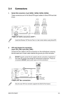
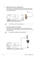
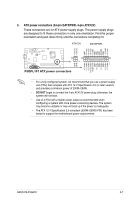
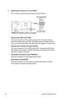
3.4 Connectors 1. Serial ATA connectors (7-pin SATA1, SATA2, SATA3, SATA4) These connectors are for the Serial ATA signal cables for Serial ATA hard disk drives. SATA1 SATA3 GND RSATA_RXP1 RSATA_RXN1 GND RSATA_TXP1 RSATA_TXN1 GND GND RSATA_RXP3 RSATA_RXN3 GND RSATA_TXP3 RSATA_TXN3 GND P5QPL10T SATA2 SATA4 GND RSATA_RXP2 RSATA_RXN2 GND RSATA_TXP2 RSATA_TXN2 GND GND RSATA_RXP4 RSATA_RXN4 GND RSATA_TXP4 RSATA_TXN4 GND P5QPL10T SATA connectors (ICH7®) Install the Windows® XP Service Pack 2 or later version before using Serial ATA. 2. CPU and chassis fan connectors. (4-pin CPU_FAN, 4-pin CHA_FAN1) Connect the fan cables to the fan connectors on the motherboard, ensuring that the black wire of each cable matches the ground pin of the connector. DO NOT forget to connect the fan cables to the fan connectors. Insufficient air flow inside the system may damage the motherboard components. These are not jumpers! DO NOT place jumper caps on the fan connectors! CPU_FAN CPU FAN PWM CPU FAN IN CPU FAN PWR GND P5QPL10T P5QPL10T fan connectors CHA_FAN1 GND CPU FAN PWR CPU FAN IN CPU FAN PWM Only the 4-pin CPU fan connector supports the ASUS Q-Fan feature. ASUS P6-P5G41E 3-5
-
 1
1 -
2
-
3
-
4
-
5
-
6
-
7
-
8
-
9
-
10
-
11
-
12
-
13
-
14
-
15
-
16
-
17
-
18
-
19
-
20
-
21
-
22
-
23
-
24
-
25
-
26
-
27
-
28
-
 29
29 -
 30
30 -
 31
31 -
 32
32 -
 33
33 -
 34
34 -
 35
35 -
 36
36 -
 37
37 -
 38
38 -
 39
39 -
40
-
41
-
42
-
43
-
44
-
45
-
46
-
47
-
48
-
49
-
50
-
51
-
52
-
53
-
54
-
55
-
56
-
57
-
58
-
59
-
60
-
61
-
62
-
63
-
64
-
65
-
66
-
67
 |
 |
