Asus P8H61-M LX User Manual - Page 23
System memory
 |
View all Asus P8H61-M LX manuals
Add to My Manuals
Save this manual to your list of manuals |
Page 23 highlights
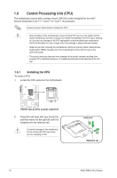
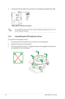
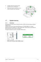
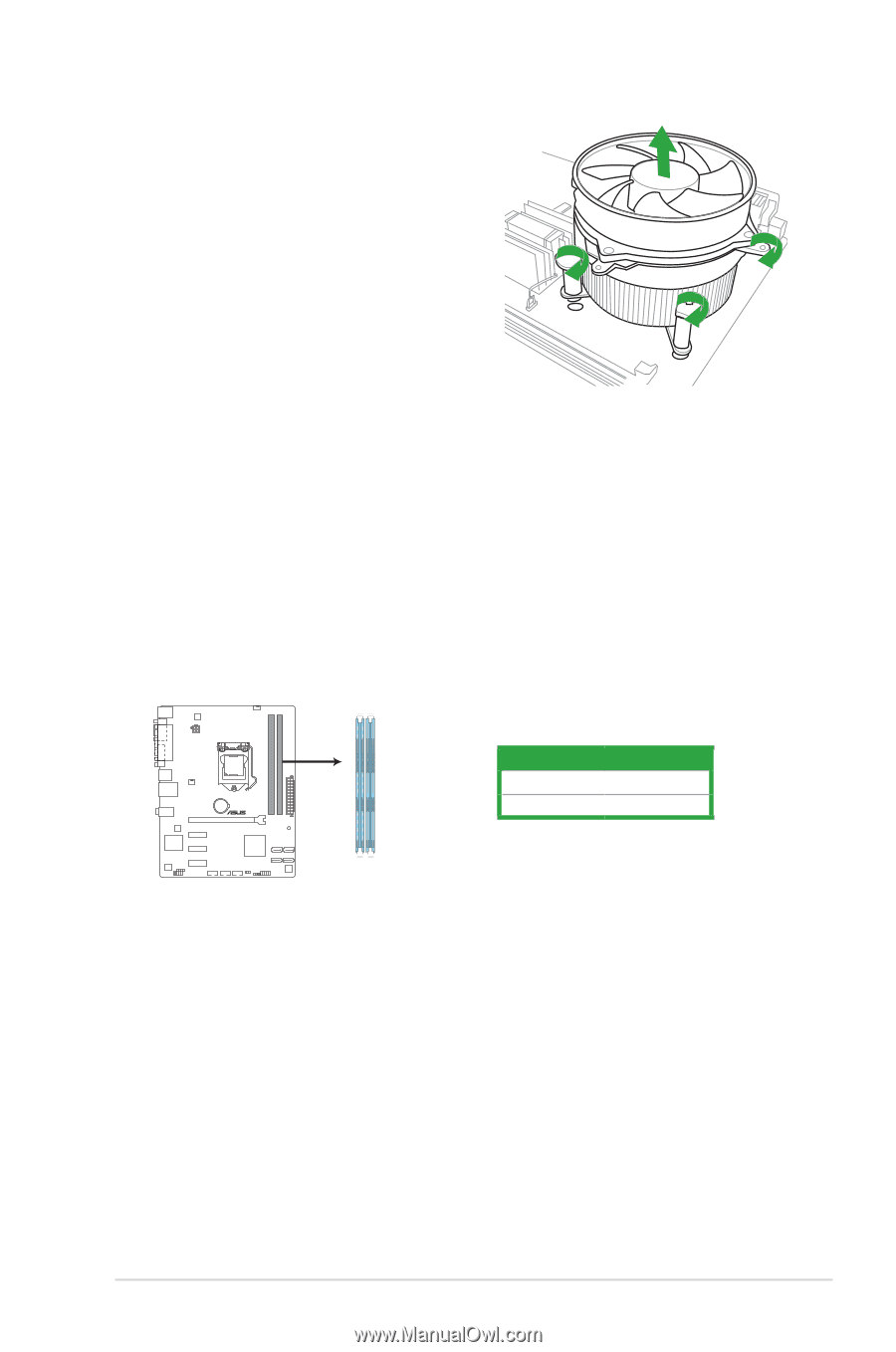
4. Carefully remove the heatsink and fan assembly from the motherboard. 5. Rotate each fastener clockwise to ensure correct orientation when reinstalling. 1.7 System memory 1.7.1 Overview The motherboard comes with two Double Data Rate 3 (DDR3) Dual Inline Memory Modules (DIMM) sockets. A DDR3 module has the same physical dimensions as a DDR2 DIMM but is notched differently to prevent installation on a DDR2 DIMM socket. DDR3 modules are developed for better performance with less power consumption. The figure illustrates the location of the DDR3 DIMM sockets: DIMM_A1 DIMM_B1 P8H61-M LX Channel Channel A Channel B Sockets DIMM_A1 DIMM_B1 P8H61-M LX 240-pin DDR3 DIMM sockets Chapter 1: Product introduction 1-13
-
 1
1 -
2
-
3
-
4
-
5
-
6
-
7
-
8
-
9
-
10
-
11
-
12
-
13
-
14
-
15
-
16
-
17
-
 18
18 -
 19
19 -
 20
20 -
 21
21 -
 22
22 -
 23
23 -
 24
24 -
 25
25 -
 26
26 -
 27
27 -
 28
28 -
29
-
30
-
31
-
32
-
33
-
34
-
35
-
36
-
37
-
38
-
39
-
40
-
41
-
42
-
43
-
44
-
45
-
46
-
47
-
48
-
49
-
50
-
51
-
52
-
53
-
54
-
55
-
56
-
57
-
58
-
59
-
60
-
61
-
62
-
63
-
64
-
65
-
66
 |
 |
1-13
Chapter 1: Product introduction
P8H61-M LX
P8H61-M LX 240-pin DDR3 DIMM sockets
DIMM_A1
DIMM_B1
1.7
System memory
1.7.1
Overview
The motherboard comes with two Double Data Rate 3 (DDR3) Dual Inline Memory Modules
(DIMM) sockets.
A DDR3 module has the same physical dimensions as a DDR2 DIMM but is notched
differently to prevent installation on a DDR2 DIMM socket. DDR3 modules are developed for
better performance with less power consumption.
The figure illustrates the location of the DDR3 DIMM sockets:
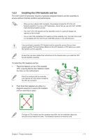
4.
Carefully remove the heatsink and fan
assembly from the motherboard.
5.
Rotate each fastener clockwise to ensure
correct orientation when reinstalling.
Channel
Sockets
Channel A
DIMM_A1
Channel B
DIMM_B1