Asus PM17TU User Manual - Page 7
Making The Connections
 |
View all Asus PM17TU manuals
Add to My Manuals
Save this manual to your list of manuals |
Page 7 highlights
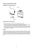
MAKING THE CONNECTIONS Connecting the Signal Cable: Plug one end of the VGA Cableto the LCD monitor's VGA port, the other end to the computer's VGA socket and tighten the two screws on the cable connector. Moreover, for MM17T, you can buy an extra 24-Pin DVI-D cable from your dealer for the digital signal connection if preferred. Connecting the Power Cord: Plug one end of the AC-power cord to the LCD monitor's AC input socket, the other end to the power outlet. Connecting the Audio Cable (MM17T only): Plug the audio cable between the computer multi-media (or audio) card's audio output and monitor's audio jack. Caution: If the AC outlet is not grounded (with three holes), install the proper grounding adapter (not supplied). Figure 2 1. AC Input Socket 3. DVI-D Port (MM17T only) 5. Earphone Jack (MM17T only) 2. Audio Jack (MM17T only) 4. VGA (D-SUB) Port 6. Cable Binder 6
-
 1
1 -
 2
2 -
 3
3 -
 4
4 -
 5
5 -
 6
6 -
 7
7 -
 8
8 -
 9
9 -
 10
10 -
 11
11 -
 12
12 -
13
-
14
-
15
-
16
-
17
-
18
 |
 |
