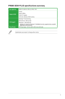
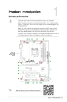
Asus PRIME B250-PLUS PRIME B250-PLUS USER S MANUAL ENGLISH - Page 13
PCI Express operating mode, PCIe 3.0/2.0 x16_1 gray, Single VGA/PCIe card, VGA configuration
 |
View all Asus PRIME B250-PLUS manuals
Add to My Manuals
Save this manual to your list of manuals |
Page 13 highlights
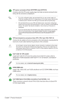
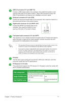
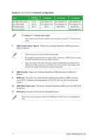
+5V SPDIFOUT GND USB 2.0 connector (10-1 pin USB1112) Connect a USB module cable to this connector, then install the module to a slot opening at the back of the system chassis. These USB connectors comply with USB 2.0 specifications and supports up to 480Mbps connection speed. Serial port connector (10-1 pin COM) Connect the serial port module cable to this connector, then install the module to a slot opening at the back of the system chassis. Digital audio connector (4-1 pin SPDIF_OUT) Connect the S/PDIF Out module cable to this connector, then install the module to a slot opening at the back of the system chassis. PIN 1 SPDIF_OUT Front panel audio connector (10-1 pin AAFP) This connector is for a chassis-mounted front panel audio I/O module that supports either HD Audio or legacy AC`97 audio standard. Connect one end of the front panel audio I/O module cable to this connector. • We recommend that you connect a high-definition front panel audio module to this connector to avail of the motherboard's high-definition audio capability. • If you want to connect a high-definition front panel audio module to this connector, set the Front Panel Type item in the BIOS setup to [HD Audio]. If you want to connect an AC'97 front panel audio module to this connector, set the item to [AC97]. By default, this connector is set to [HD Audio]. PCI slots The PCI slots support cards such as LAN card, SCSI card, USB card, and other cards that comply with the PCI specifications PCI Express 3.0 x16 slots This motherboard supports two PCI Express 3.0 x16 graphic cards that comply with the PCI Express specifications. VGA configuration Single VGA/PCIe card Dual VGA/PCIe cards PCI Express operating mode PCIe 3.0/2.0 x16_1 (gray) PCIe 3.0/2.0 x16_2 x16 (Recommended for single VGA card) N/A x16 x4 (shares bandwidth with M.2_1) Chapter 1: Product introduction 1-4
-
 1
1 -
2
-
3
-
4
-
5
-
6
-
7
-
 8
8 -
 9
9 -
 10
10 -
 11
11 -
 12
12 -
 13
13 -
 14
14 -
 15
15 -
 16
16 -
 17
17 -
 18
18 -
19
-
20
-
21
-
22
-
23
-
24
-
25
-
26
-
27
-
28
 |
 |
