Asus Pro A520M-C/CSM Pro A520M-C Users Manual English - Page 14
Rear panel connectors, Video Graphics Adapter VGA port.
 |
View all Asus Pro A520M-C/CSM manuals
Add to My Manuals
Save this manual to your list of manuals |
Page 14 highlights
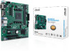
1.2.2 Rear panel connectors 1 2 3 4 5 67 8 9 10 11 12 1. PS/2 Mouse port (green). This port is for a PS/2 mouse. 2. Video Graphics Adapter (VGA) port. This 15-pin port is for a VGA monitor or other VGA-compatible devices. 3. Serial port connector (COM). This port connects a modem, or other devices that conform with serial specification. 4. USB 3.2 Gen 1 (up to 5Gbps) ports. These 9-pin Universal Serial Bus (USB) ports connect to USB 3.2 Gen 1 devices. 5. Ethernet port. This port allows Gigabit connection to a Local Area Network (LAN) through a network hub. Refer to the table below for the Ethernet port LED indications. Ethernet port LED indications Activity/Link LED Status Description Off No link Speed LED Status Description Off 10Mbps connection Activity Link Speed LED LED Orange Linked Orange 100Mbps connection Orange (Blinking) Data activity Green Orange (Blinking Ready to wake then steady) up from S5 mode 1Gbps connection Ethernet port 6. Line In port (light blue). This port connects the tape, CD, DVD player, or other audio sources. 7. Line Out port (lime). This port connects a headphone or a speaker. In 4-channel, 5.1-channel, and 7.1-channel configurations, the function of this port becomes Front Speaker Out. 8. PS/2 Keyboard port (purple). This port is for a PS/2 keyboard. 9. DVI-D port. This port is for any DVI-D compatible device. DVI-D can not be converted to output from RGB Signal to CRT and is not compatible with DVI-I. 1-6 Chapter 1: Product Introduction
-
 1
1 -
2
-
3
-
4
-
5
-
6
-
7
-
8
-
 9
9 -
 10
10 -
 11
11 -
 12
12 -
 13
13 -
 14
14 -
 15
15 -
 16
16 -
 17
17 -
 18
18 -
 19
19 -
20
-
21
-
22
-
23
-
24
-
25
-
26
-
27
-
28
 |
 |
