Asus Pro WS W790E-SAGE SE Users Manual English - Page 17
Pro WS W790E-SAGE SE, Layout contents
 |
View all Asus Pro WS W790E-SAGE SE manuals
Add to My Manuals
Save this manual to your list of manuals |
Page 17 highlights
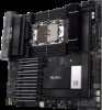
Layout contents 1. CPU socket 2. DIMM slots 3. Expansion slots 4. Fan headers 5. Power connectors 6. M.2 slot 7. Micro SD card socket 8. SATA 6GB/s port 9. SlimSAS port 10. USB 3.2 Gen 2 Type-C® Front Panel connector 11. USB 3.2 Gen 1 header 12. USB 2.0 connector 13. BMC switch 14. BMC Thermal Sensor header 15. COM Port header 16. Fixed Dedicated BMC LAN IP switch 17. FlexKey button (Reset) 18. Front Panel Audio header 19. IPMI switch 20. LED headers 21. LN2 Mode jumper 22. Location button and LED headers 23. M.2 slot (Key E) 24. Power Supply SMBus connector 25. ReTry button 26. Safe Boot button 27. SMART PSU switch 28. Start button 29. System Panel header 30. Thermal Sensor header 31. TPM header 32. VGA Switch 33. VPP_I2C header 34. VROC Key header 35. Q-Code LED 36. Q LEDs 37. BMC LED 38. Location LED 39. Message LED 40. Processor Catastrophic Error LED 41. 8-pin Power Plug LED 42. 8-pin PCIe Power Plug LED Pro WS W790E-SAGE SE Page 1-4 1-5 1-7 1-9 1-10 1-11 1-12 1-13 1-13 1-14 1-14 1-15 1-15 1-16 1-16 1-17 1-17 1-18 1-18 1-19 1-19 1-20 1-20 1-21 1-21 1-22 1-22 1-23 1-24 1-25 1-25 1-26 1-26 1-27 1-28 1-29 1-29 1-30 1-30 1-31 1-31 1-32 1-3 Chapter 1
-
 1
1 -
2
-
3
-
4
-
5
-
6
-
7
-
8
-
9
-
10
-
11
-
 12
12 -
 13
13 -
 14
14 -
 15
15 -
 16
16 -
 17
17 -
 18
18 -
 19
19 -
 20
20 -
 21
21 -
 22
22 -
23
-
24
-
25
-
26
-
27
-
28
-
29
-
30
-
31
-
32
-
33
-
34
-
35
-
36
-
37
-
38
-
39
-
40
-
41
-
42
-
43
-
44
-
45
-
46
-
47
-
48
-
49
-
50
-
51
-
52
-
53
-
54
-
55
-
56
-
57
-
58
-
59
-
60
-
61
-
62
-
63
-
64
-
65
-
66
-
67
-
68
-
69
-
70
-
71
-
72
-
73
-
74
-
75
-
76
-
77
-
78
-
79
-
80
-
81
-
82
-
83
-
84
-
85
-
86
-
87
-
88
-
89
-
90
-
91
-
92
-
93
-
94
-
95
-
96
 |
 |
