Asus RS161-E4 User Manual
Asus RS161-E4 - 0 MB RAM Manual
 |
UPC - 610839640652
View all Asus RS161-E4 manuals
Add to My Manuals
Save this manual to your list of manuals |
Asus RS161-E4 manual content summary:
- Asus RS161-E4 | User Manual - Page 1
RS161-E2/PA2 1U Rackmount Barebone Server User Guide - Asus RS161-E4 | User Manual - Page 2
, and should not be construed as a commitment by ASUS. ASUS assumes no responsibility or liability for any errors or inaccuracies that may appear in this manual, including the products and software described in it. Product warranty or service will not be extended if: (1) the product is repaired - Asus RS161-E4 | User Manual - Page 3
Safety information viii About this guide ix Chapter 1: Product introduction Motherboard information 2-4 2.3 Central Processing Unit (CPU 2-5 2.3.1 Overview 2-5 2.3.2 Installing the CPU 2-5 2.3.3 Installing the heatsink and airduct 2-7 2.4 System memory 2-9 2.4.1 Overview 2-9 2.4.2 Memory - Asus RS161-E4 | User Manual - Page 4
the server 3-4 Chapter 4: Motherboard information 4.1 Motherboard layout 4-2 4.2 Jumpers 4-4 4.3 Internal connectors 4-8 Chapter 5: BIOS setup 5.1 Managing and updating your BIOS 5-2 5.1.1 Creating a bootable floppy disk 5-2 5.1.2 AFUDOS utility 5-3 5.1.3 ASUS CrashFree BIOS 2 utility - Asus RS161-E4 | User Manual - Page 5
menu 5-20 5.4.1 CPU Configuration 5-20 5.4.2 Chipset Configuration 5-21 5.4.3 Server menu 5-30 5.6 Security menu 5-32 5.7 Boot menu 5-35 5.7.1 Boot Device Priority 5-35 5.7.2 Boot Settings Configuration 5-36 5.8 Exit menu 5-38 Chapter 6: RAID configuration 6.1 Setting up RAID 6-2 6.1.1 RAID - Asus RS161-E4 | User Manual - Page 6
Contents 6.2 NVIDIA® RAID configurations 6-4 6.2.1 Setting the BIOS RAID items 6-4 6.2.2 Entering the NVIDIA® RAID Utility 6-5 6.2.3 Creating a RAID 0 set (Stripe 6-6 6.2.4 Creating a RAID 1 set (Mirror 6-8 6.2.5 Rebuilding a RAID set 6-9 6.2.6 Deleting a RAID array 6-10 6.2.7 Clearing the - Asus RS161-E4 | User Manual - Page 7
. This equipment generates, uses and can radiate radio frequency energy and, if not installed and used in accordance with manufacturer's instructions, may cause harmful interference to radio communications. However, there is no guarantee that interference will not occur in a particular installation - Asus RS161-E4 | User Manual - Page 8
by yourself. Contact a qualified service technician or your dealer. Operation Safety • Any mechanical operation on this server must be conducted by certified or experienced engineers. • Before operating the server, carefully read all the manuals included with the server package. • Before using the - Asus RS161-E4 | User Manual - Page 9
optional components into the barebone server. 4 . Chapter 4: Motherboard information This chapter gives information about the motherboard that comes with the server. This chapter includes the motherboard layout, jumper settings, and connector locations. 5. Chapter 5: BIOS information This chapter - Asus RS161-E4 | User Manual - Page 10
A N T : Instructions that you MUST follow to value enclosed in brackets. Example: At the DOS prompt, type the command line: format A:/S Refer to the following sources for additional information, and for product and software updates. 1 . ASUS Server Web-based Management (ASWM) user guide This manual - Asus RS161-E4 | User Manual - Page 11
Product introduction Chapter 1 This chapter describes the general features of the chassis kit. It includes sections on front panel and rear panel specifications. ASUS RS161-E2/PA2 1-1 - Asus RS161-E4 | User Manual - Page 12
package for the following standard items. 1. ASUS R10 1U rackmount chassis with: • ASUS K8N-DRE motherboard • 500 W power supply • SATA backplane CPU heatsink 3. SATA cables 4. IDE cable 5. Rackmount rail kit 6. Bundled CDs • RS161-E2 drivers and utilities CD • CA Anti-virus software CD 7. User guide - Asus RS161-E4 | User Manual - Page 13
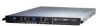
The ASUS RS161-E2 (PA2) is a 1U barebone server system featuring the ASUS K8N-DRE motherboard. The server supports dual 940-pin AMD Opteron™ 64 processors, and includes the latest technologies through the chipsets embedded on the motherboard. Chassis Rackmount 1U (R10) Motherboard ASUS K8N - Asus RS161-E4 | User Manual - Page 14
1.3 Front panel features The barebone server displays a simple yet stylish front panel with easily accessible middle part includes the I/O shield with openings for the rear panel connectors on the motherboard. The ports for the PS/2 keyboard, PS/2 mouse, USB, VGA, and Gigabit LAN do not - Asus RS161-E4 | User Manual - Page 15
HDD tray 2 10. Front I/O board (hidden) 7 11. Optical drive 8 9 11 10 The barebone server does not include a floppy disk drive. Connect an external floppy disk drive (USB interface) to any of the USB ports on the front or rear panel if you need to use a floppy disk. ASUS RS161-E2/PA2 1-5 - Asus RS161-E4 | User Manual - Page 16
1.6 LED information 1.6.1 Front panel LEDs LED Power LED HDD Access LED Power LED LAN2 LED Location LED Message LED LAN1 LED Icon Display status Description ON System power ON HDD Access LED OFF Blinking No activity Read/write data into the HDD Message LED Location LED LAN LEDs OFF - Asus RS161-E4 | User Manual - Page 17
Chapter 2 This chapter lists the hardware setup procedures that you have to perform when installing or removing system components. Hardware setup ASUS RS161-E2/PA2 2-1 - Asus RS161-E4 | User Manual - Page 18
2.1 Chassis cover 2.1.1 Removing the cover 1. Use a Phillips screwdriver to remove the screw on each front end of the top cover. 2. Loosen the two thumbscrews on the rear panel to release the top cover from the chassis. 3. Remove the screws on both sides of the chassis. Thumbscrews 4. Firmly hold - Asus RS161-E4 | User Manual - Page 19
it snaps in place. 4. Tighten the thumbscrews on the rear to secure the cover. Thumbscrews 5. Drive in the screw on both sides of the chassis. ASUS RS161-E2/PA2 2-3 - Asus RS161-E4 | User Manual - Page 20
information The barebone server comes with the K8N-DRE motherboard already installed. The motherboard is secured to the chassis by 10 screws as indicated by the circles in the illustration below. Refer to "Chapter 4 Motherboard information" for detailed information on the motherboard. K8N-DRE - Asus RS161-E4 | User Manual - Page 21
corner on the socket to ensure correct installation. Notched corner 2.3.2 Installing the CPU To install a CPU: 1. Locate the CPU socket on the motherboard. K8N-DRE ¤ CPU2 CPU1 CPU2 CPU1 K8N-DRE CPU Socket 940 If installing only one CPU, use the CPU socket marked CPU1. ASUS RS161-E2/PA2 2-5 - Asus RS161-E4 | User Manual - Page 22
the socket to prevent bending the pins and damaging the CPU! 5. When the CPU is in place, push down the socket lever to secure the CPU. The lever clicks on the side tab to indicate that it is locked. 6. Repeat steps 1-5 to install a second processor in CPU 2 socket. 2-6 Chapter 2: Hardware setup - Asus RS161-E4 | User Manual - Page 23
screw holes match with the support plate stand offs. 2. Secure the heatsink with two screws. Make sure that the heatsink is not skewed or tilted; otherwise, the CPU will overheat. 3. If you installed a second processor, repeat steps 1 and 2 to install the second heatsink. ASUS RS161-E2/PA2 2-7 - Asus RS161-E4 | User Manual - Page 24
To install the airduct: 1. Position the airduct on top of the heatsink. 2. Carefully lower the airduct until it fits in place. 2-8 Chapter 2: Hardware setup - Asus RS161-E4 | User Manual - Page 25
2.4 System memory 2.4.1 Overview The motherboard comes with eight 184-pin Double Data Rate (DDR) Dual Inline Memory Modules (DIMM CPU 1 Channel A Channel B For CPU 2 Channel A Channel B Sockets DIMM_A1 and DIMM_A2 DIMM_B1 and DIMM_B2 Sockets DIMM_C1 and DIMM_C2 DIMM_D1 and DIMM_D2 ASUS RS161-E2/PA2 - Asus RS161-E4 | User Manual - Page 26
in this section. • For dual-channel configuration, the total size of memory module(s) installed per channel must be the same for better performance. Single CPU: DIMM_A1=DIMM_A2=DIMM_B1=DIMM_B2 Dual CPU: DIMM_A1=DIMM_A2=DIMM_B1=DIMM_B2= DIMM_C1=DIMM_C2 =DIMM_D1=DIMM_D2 • Always install DIMMs - Asus RS161-E4 | User Manual - Page 27
If you install a processor with Rev. CG or C0 with DDR 400 DIMMs, some memory configurations may not run at 400 MHz. Refer to table below for details. Mode Single rank DDR400 Double rank DDR400 Single rank DDR400 Double rank DDR400 Single rank DDR400 Double rank DDR333 ASUS RS161-E2/PA2 2-11 - Asus RS161-E4 | User Manual - Page 28
2.5 Hard disk drives The system supports two hot-swap Serial ATA hard disk drives. To install a hot-swap SATA HDD: 1. Release a drive tray by pushing the spring lock to the right, - Asus RS161-E4 | User Manual - Page 29
the bundled SATA cables to the connectors on the SATA backplane. Refer to section "2.8 SATA backplane cabling" for information on the SATA backplane cable connections. ASUS RS161-E2/PA2 2-13 - Asus RS161-E4 | User Manual - Page 30
barebone server comes with a riser card bracket. You need to remove the bracket if you want to install PCI Express x16 expansion cards. To install the PCI Express x16 expansion cards: 1. Firmly hold the riser card bracket, then pull it up to detach it from the PCI Express x16 slot on the motherboard - Asus RS161-E4 | User Manual - Page 31
Install the riser card bracket with the card into the PCI Express x16 slot on the motherboard. 3. Press the riser card bracket until the golden connectors completely fit the slot and the bracket aligns with the rear panel. 4. Connect the cable(s) to the card, if applicable. ASUS RS161-E2/PA2 2-15 - Asus RS161-E4 | User Manual - Page 32
Turn on the system and change the necessary BIOS settings, if any. See Chapter 5 for information on BIOS setup. 2. Assign an IRQ to the card. holder for PCI steering* PS/2 Compatible Mouse Port* Numeric Data Processor Primary IDE Channel Secondary IDE Channel *These IRQs are usually available for - Asus RS161-E4 | User Manual - Page 33
(from backplane to device fan) 6. SATA connectors (from motherboard to SATA backplane board) 7. USB connector (from motherboard to front I/O board) 8. Panel connector (from motherboard to front I/O board) 9. Auxiliary panel connector (from motherboard to front I/O board) ASUS RS161-E2/PA2 2-17 - Asus RS161-E4 | User Manual - Page 34
2.8 SATA backplane cabling Connects the SMBus cable from the MB Connects the SATA cable from SATA1 on the MB Connects a 4-pin plug from power supply Connects the fan cable from FRNT_FAN4 on the MB Connect the system fan cables Connects the SATA cable from SATA2 on the MB Connect the SATA HDDs - Asus RS161-E4 | User Manual - Page 35
the following components: 1. System fans 2. Device fan 3. Power supply module 4. Optical drive 5. Motherboard 2.9.1 System fans To uninstall the system fans: 1. Disconnect a system fan cable from the fan the system fan cable to the fan connector on the backplane board. ASUS RS161-E2/PA2 2-19 - Asus RS161-E4 | User Manual - Page 36
2.9.2 Device fan To uninstall the device fan: 1. Disconnect the device fan cable 2. Lift the fan, then set aside. from the connector on the motherboard or backplane board. To reinstall the device fan: 1. Insert the fan to the fan cage. Take note of the airflow directional arrows embossed on the - Asus RS161-E4 | User Manual - Page 37
the memory module(s) comes with a dummy case that allows it to fit in the fan cage. Follow these instructions when replacing this fan. 1. Uninstall the fan following the instructions in the 3. Reinstall the device fan by following the instructions in the previous section. ASUS RS161-E2/PA2 2-21 - Asus RS161-E4 | User Manual - Page 38
2.9.4 Power supply module To uninstall the power supply module: 1. Disconnect all the power cables connected to the motherboard and other system devices. 2. Use a Phillips (cross) screwdriver to remove the screws that secure the front end of the power supply. 3. From the rear panel, - Asus RS161-E4 | User Manual - Page 39
sides (B) to remove. Do not apply too much force when removing the bezel. Too much force may break the drive tray! 5. Replace the drive tray. ASUS RS161-E2/PA2 2-23 - Asus RS161-E4 | User Manual - Page 40
6. Remove two metal bracket screws and screws on the other side of the drive. Keep the screws for later use. 7. Pull the metal bracket to the direction of the arrow until its pegs disengage from the drive holes. 8. Lift the metal bracket, then set aside. 9. Push the drive inward, then lift it out - Asus RS161-E4 | User Manual - Page 41
these components. 3. Use a Phillips (cross) screwdriver to remove the screws that secure the motherboard to the base of the chassis. Refer to the illustration below for the location of the motherboard screws. K8N-DRE ¤ 4. Carefully lift the motherboard out of the chassis. ASUS RS161-E2/PA2 2-25 - Asus RS161-E4 | User Manual - Page 42
by the sides and insert it into the chassis. 2. Carefully adjust the motherboard until the rear panel ports fit in place. 3. Use a Phillips (cross) screwdriver to secure the motherboard with 10 screws in the holes as shown in the illustration. K8N-DRE ¤ 4. Reconnect all the required cables - Asus RS161-E4 | User Manual - Page 43
Installation options Chapter 3 This chapter describes how to install the optional components and devices into the barebone server. ASUS RS161-E2/PA2 2-1 - Asus RS161-E4 | User Manual - Page 44
3.1 Rackmount rail kit items If you have the rackmount rail kit, it contains two pairs of rails (one pair for each side of the barebone system), and eight (8) pairs of nut-and-bolt type screws. Nuts Bolts Left pair Right pair 3.2 Rack rails assembly To assemble the rack rails: 1. Determine - Asus RS161-E4 | User Manual - Page 45
end holes. 7. Drive in two screws on the outer holes to secure the rear end. 8. From the rack front, find the corresponding 1U space for the second rail pair. 9. Repeat steps 2 to 7 to attach the second rail pair. When properly installed, the rack rails appear as shown. ASUS RS161-E2 (PA2) 3-3 - Asus RS161-E4 | User Manual - Page 46
panel side to the front end of the rack rail, then carefully push the server all the way to the back until the front panel fits the front end of the rack, and the rack screws on the server match the middle hole on the rack.. 2. Tighten the two rack screws to - Asus RS161-E4 | User Manual - Page 47
Motherboard info Chapter 4 This chapter gives information about the motherboard that comes with the server. This chapter includes the motherboard layout, jumper settings, and connector locations ASUS RS161-E2/PA2 2-1 - Asus RS161-E4 | User Manual - Page 48
REAR_FAN1 REAR_FAN2 REAR_FAN3 REAR_FAN4 SEC_IDE1 PRI_IDE1 PSUSMB1 ATX12V1 ATXPWR1 4.1 Motherboard layout 30.5cm (12in) Super I/O 8Mbit BIOS BUZZ1 J1 RECOVERY1 K8N-DRE LAN2 BMCSOCKET1 BCM5721 LAN1 VGA1 COM1 USB12 KBMS1 KBPWR1 BCM5721 LAN2_EN1 LAN1_EN1 COM2 CPU_WARN1 LPT1 PCI1 - Asus RS161-E4 | User Manual - Page 49
controller setting (3-pin LAN2_EN1) 5. VGA graphics controller setting (3-pin VGA_EN1) 6. BIOS recovery setting (3-pin RECOVERY1) Internal connectors 1. Floppy disk drive connector (34-1 4-5 4-5 4-6 4-6 4-7 Page 4-8 4-8 4-9 4-10 4-10 4-11 4-12 4-12 4-13 4-14 4-14 4-15 4-16 ASUS RS161-E2 (PA2) 4-3 - Asus RS161-E4 | User Manual - Page 50
the Real Time Clock (RTC) RAM in CMOS. You can clear the CMOS memory of date, time, and system setup parameters by erasing the CMOS RTC RAM cord and turn ON the computer. 6. Hold down the key during the boot process and enter BIOS setup to re-enter data. Except when clearing the RTC RAM, never - Asus RS161-E4 | User Manual - Page 51
pins 1-2 (+5VSB) to wake up the computer when you press a key on the keyboard (the default is the Space Bar). This feature at least 1A on the +5VSB lead, and a corresponding setting in the BIOS. K8N-DRE ¤ KBPWR1 1 2 +5VSB 2 3 +5V (Default) K8N K8N-DRE LAN1_EN1 setting ASUS RS161-E2 (PA2) 4-5 - Asus RS161-E4 | User Manual - Page 52
Rage XL video graphics controller. Set to pins 1-2 to enable the video graphics controller. K8N-DRE ¤ VGA_EN1 1 2 Enable (Default) 2 3 Disable K8N-DRE VGA setting 4-6 Chapter 4: Motherboard info - Asus RS161-E4 | User Manual - Page 53
computer. 7. Replace the jumper cap from pins 2-3 to pins 1-2. 8. Reboot your computer. 9. Hold down the key during the boot process and enter BIOS setup to re-enter data. K8N-DRE ¤ RECOVERY1 1 2 Normal (Default) 2 3 BIOS recovery K8N-DRE BIOS recovery setting ASUS RS161-E2 (PA2) 4-7 - Asus RS161-E4 | User Manual - Page 54
133/100/66 signal cables. The Ultra DMA 133/100/66 signal cable has three connectors: a blue connector for the primary IDE connector on the motherboard, a black connector for an Ultra DMA 133/100/66 IDE slave device (optical drive/hard disk drive), and a gray connector for an Ultra DMA 133 - Asus RS161-E4 | User Manual - Page 55
Supported by the NVIDIA® nForce4™ chipset, these connectors are for the Serial ATA signal cables for Serial ATA hard disk drives that allows up to 3Gb/s of data transfer rate. If you installed Serial ATA hard disk drives, you can create a RAID 0, RAID RSATA_RXP3 GND ASUS RS161-E2 (PA2) 4-9 - Asus RS161-E4 | User Manual - Page 56
SMBus host and /or other SMBus devices using the SMBus interface. K8N-DRE ¤ K8N-DRE SMBus connector FPSMB 1 FAN_PWM I2C_CLK# GND I2C_DATA# +5VSB 4-10 Chapter 4: Motherboard info - Asus RS161-E4 | User Manual - Page 57
) The fan connectors support cooling fans of 350mA~2000mA (24 W max.) or a total of 1A~3.48A (41.76 W max.) at +12V. Connect the fan cables to the fan connectors on the motherboard, making sure that Rotation +12V GND Rotation +12V GND Rotation +12V GND Rotation +12V GND ASUS RS161-E2 (PA2) 4-11 - Asus RS161-E4 | User Manual - Page 58
USB34) This connector is for USB 2.0 ports. This connector complies with the USB 2.0 specification that supports up to 480 Mbps connection speed. K8N-DRE ¤ USB34 1 USB+5V USB_P3USB_P3+ GND USB+5V USB_P4USB_P4 COM2 PIN 1 K8N-DRE Serial port2 (COM2) connector 4-12 Chapter 4: Motherboard info - Asus RS161-E4 | User Manual - Page 59
Power OK +5V Standby +12 Volts +12 Volts +3 Volts 12V GND 12V GND 12V GND 12V GND For Power Supply with 20-pin Power Connector ASUS RS161-E2 (PA2) 4-13 - Asus RS161-E4 | User Manual - Page 60
SPD6 SPD7 ACK# BUSY PE SLCT AFD# ERROR# PINIT# SLIN# GND GND GND GND GND GND GND GND K8N-DRE Parallel port connector 4-14 Chapter 4: Motherboard info - Asus RS161-E4 | User Manual - Page 61
12. System panel auxiliary connector (20-pin AUX_PANEL1) This connector supports several server system functions. K8N-DRE ¤ K8N-DRE Auxiliary panel connector AUX_PANEL1 1 +5VSB communicate with an SMBus host and/or other SMBus devices using the SMBus interface. ASUS RS161-E2 (PA2) 4-15 - Asus RS161-E4 | User Manual - Page 62
panel connector (20-pin PANEL1) This connector supports several chassis-mounted functions. K8N-DRE PANEL1 ¤ ON or puts the system in SLEEP or SOFT-OFF mode depending on the BIOS settings. Pressing the power switch for more than four seconds while the system is 4-16 Chapter 4: Motherboard info - Asus RS161-E4 | User Manual - Page 63
BIOS setup Chapter 5 This chapter tells how to change the system settings through the BIOS Setup menus. Detailed descriptions of the BIOS parameters are also provided. ASUS RS161-E2/PA2 - Asus RS161-E4 | User Manual - Page 64
manage and update the motherboard Basic Input/Output System (BIOS) setup. 1. A S U S A F U D O S (Updates the BIOS in DOS mode using a bootable floppy disk.) 2. A S U S C r a s h F r e e B I O S 2 (Updates the BIOS using a bootable floppy disk or the motherboard support CD when the BIOS file fails - Asus RS161-E4 | User Manual - Page 65
/oOLDBIOS1.rom AMI Firmware Update Utility - Version 1.19(ASUS V2.07(03.11.24BB)) Copyright (C) 2002 American Megatrends, Inc. All rights reserved. Reading flash ..... done Write to file...... ok A:\> The utility returns to the DOS prompt after copying the current BIOS file. ASUS RS161-E2/PA2 5-3 - Asus RS161-E4 | User Manual - Page 66
Updating the BIOS file To update the BIOS file using the AFUDOS utility: 1. Visit the ASUS website (www.asus.com) and download the latest BIOS file for the motherboard. Save the BIOS file to a bootable floppy disk. Write the BIOS filename on a piece of paper. You need to type the exact BIOS filename - Asus RS161-E4 | User Manual - Page 67
Megatrends, Inc. All rights reserved. WARNING!! Do not turn off power during flash BIOS Reading file ....... done Reading flash ...... done Advance Check ...... Erasing flash ...... done Writing flash ...... done Verifying flash .... done Please restart your computer A:\> ASUS RS161-E2/PA2 5-5 - Asus RS161-E4 | User Manual - Page 68
2 utility The ASUS CrashFree BIOS 2 is an auto recovery tool that allows you to restore the BIOS file when it fails or gets corrupted during the updating process. You can update a corrupted BIOS file using the motherboard support CD or the floppy disk that contains the updated BIOS file. • Prepare - Asus RS161-E4 | User Manual - Page 69
updating the BIOS! Doing so can cause system boot failure! 4. Restart the system after the utility completes the updating process. The recovered BIOS may not be the latest BIOS version for this motherboard. Visit the ASUS website (www.asus.com) to download the latest BIOS file. ASUS RS161-E2/PA2 - Asus RS161-E4 | User Manual - Page 70
the BIOS version information. This utility is available in the support CD that comes with the motherboard package. ASUS Update requires an Internet connection either through a network or an Internet Service Provider (ISP). Installing ASUS Update To install ASUS Update: 1. Place the support CD in - Asus RS161-E4 | User Manual - Page 71
d a t e. The ASUS Update main window appears. 2. Select U p d a t e B I O S f r o m 3. Select the ASUS FTP site t h e I n t e r n e t option from the nearest you to avoid network drop-down menu, then click traffic, or click A u t o S e l e c t. N e x t. Click N e x t. ASUS RS161-E2/PA2 5-9 - Asus RS161-E4 | User Manual - Page 72
the screen instructions to complete the update process. The ASUS Update utility is capable of updating itself through the Internet. Always update the utility to avail all its features. Updating the BIOS through a BIOS file To update the BIOS through a BIOS file: 1. Launch the ASUS Update utility - Asus RS161-E4 | User Manual - Page 73
the Exit Menu. See section "5.7 Exit Menu." • The BIOS setup screens shown in this section are for reference purposes only, and may not exactly match what you see on your screen. • Visit the ASUS website (www.asus.com) to download the latest BIOS file for this motherboard. ASUS RS161-E2/PA2 5-11 - Asus RS161-E4 | User Manual - Page 74
ESC Exit V00.00 (C)Copyright 1985-2004, American Megatrends, Inc. Sub-menu items Navigation keys 5.2.2 Menu bar The menu bar on top of the screen has the following main items: Main Advanced Server Security Boot Exit For changing the basic system configuration For changing the advanced system - Asus RS161-E4 | User Manual - Page 75
when selected. To change the value of a field, select it keys or / keys to display the other items on the screen. Pop-up window 5.2.9 General help Scroll bar At the top right corner of the menu screen is a brief description of the selected item. ASUS RS161-E2/PA2 - Asus RS161-E4 | User Manual - Page 76
screen appears, giving you an overview of the basic system information. Refer to section "5.2.1 BIOS menu screen" for information on the menu screen items and how to navigate through them. Main Advanced Server System Date System Time Floppy A: IDE Configuration Primary IDE Master Primary IDE Slave - Asus RS161-E4 | User Manual - Page 77
nVidia RAID ROM Main Configuration nVidia RAID ROM RAID Option ROM BIOS SETUP UTILITY [Disabled] →← Select Screen ↑↓ Select Item +- Change Field Tab Select Field F1 General Help F10 Save and Exit ESC Exit V00.00 (C)Copyright 1985-2004, American Megatrends, Inc. ASUS RS161-E2/PA2 5-15 - Asus RS161-E4 | User Manual - Page 78
options: [Disabled] [Enabled] Fifth Master as RAID [Disabled] Sets the fifth master interface as RAID. Configuration options: [Disabled] [Enabled] Sixth Master as RAID [Disabled] Sets the sixth master interface as RAID. Configuration options: [Disabled] [Enabled] 5-16 Chapter 5: BIOS setup - Asus RS161-E4 | User Manual - Page 79
, American Megatrends, Inc. The BIOS automatically detects the values opposite the dimmed items (Device, supports multi-sector transfer feature. When set to [Disabled], the data transfer from and to the device occurs one sector at a time. Configuration options: [Disabled] [Auto] ASUS RS161-E2/PA2 - Asus RS161-E4 | User Manual - Page 80
automatically detects the items in this menu. Main BIOS SETUP UTILITY System Information Model Name Model ID ASUS K8N-DRE/SCSI 8009A0 ASUS BIOS Version Date 1001.007 06/09/2005 Processor System Memory →← Select Screen ↑↓ Select Item +- Change Field Tab Select Field F1 General Help F10 Save - Asus RS161-E4 | User Manual - Page 81
: Speed N/A DIMM05 - None DIMM06 - None DIMM07 - None DIMM08 - None BIOS SETUP UTILITY →← Select Screen ↑↓ Select Item +- Change Field Tab Select Field F1 General Help F10 Save and Exit ESC Exit V00.00 (C)Copyright 1985-2004, American Megatrends, Inc. ASUS RS161-E2/PA2 5-19 - Asus RS161-E4 | User Manual - Page 82
cause the system to malfunction. Main Advanced Server BIOS SETUP UTILITY Security Boot Exit WARNING: Setting wrong values in the sections below may cause system to malfunction. Options for CPU. CPU Configuration Chipset Configuration PCI/PnP Configuration USB Configuration Peripheral Devices - Asus RS161-E4 | User Manual - Page 83
Burst Length SoftWare Memory Hole DRAM ECC Enable NUMA Function [4 Beats] [Enabled] [Enabled] [Enabled] →← Select Screen ↑↓ Select Item +- Change Field Tab Select Field F1 General Help F10 Save and Exit ESC Exit V00.00 (C)Copyright 1985-2004, American Megatrends, Inc. ASUS RS161-E2/PA2 5-21 - Asus RS161-E4 | User Manual - Page 84
the non-uniform memory access (NUMA) BIOS SETUP UTILITY [Disabled] →← Select Screen ↑↓ Select Item +- Change Field Tab Select Field F1 General Help F10 Save and Exit ESC Exit V00.00 (C)Copyright 1985-2004, American Megatrends, Inc. CPU Spread Spectrum [Disabled] Sets or disables the processor - Asus RS161-E4 | User Manual - Page 85
memory size block for legacy ISA devices. Take caution when changing the settings of the PCI PnP menu items. Incorrect field values : [No] [Yes] Plug And Play O/S [No] When set to [No], BIOS configures all the devices in the system. When set to [Yes] and if you install ASUS RS161-E2/PA2 5-23 - Asus RS161-E4 | User Manual - Page 86
Suport Legacy USB Support USB 2.0 Controller Mode BIOS EHCI Hand-Off BIOS SETUP UTILITY [USB l e d items show the auto-detected values. If no USB device is detected, the U S B D e v i c e s E n a b l e d item shows N o n e. USB Controller Support [USB 1.1+USB 2.0] Sets or disables the USB - Asus RS161-E4 | User Manual - Page 87
or disables the BIOS EHCI hand-off support. Configuration options: [Disabled] [Enabled] 5.4.5 Peripheral Devices Configuration Advanced BIOS SETUP UTILITY Peripheral select the Parallel Port mode. Configuration options: [Normal] [Bi-directional] [ECP] [EPP] [ECP & EPP] ASUS RS161-E2/PA2 5-25 - Asus RS161-E4 | User Manual - Page 88
the Parallel port IRQ. Configuration options: [IRQ5] [IRQ7] 5.4.6 ACPI Configuration Advanced ACPI Configuration ACPI 2.0 Features Headless Mode ACPI EMS Support BIOS SETUP UTILITY [No] [Disabled] [Disabled] →← Select Screen ↑↓ Select Item +- Change Field Tab Select Field F1 General Help F10 - Asus RS161-E4 | User Manual - Page 89
by PS/2 Mouse Resume by Ring Resume by PME# Resume by RTC BIOS SETUP UTILITY [Power Off] [Enabled] [Disabled] [Disabled] [Enabled State] Resume By PS/2 Keyboard [Enabled] Allows you to use specific keys on the keyboard to turn on the system. This feature requires an ATX ] ASUS RS161-E2/PA2 5-27 - Asus RS161-E4 | User Manual - Page 90
appear with set values. Configuration options: [Disabled] [Enabled] 5.4.8 Hardware Monitor Advanced BIOS SETUP UTILITY motherboard and CPU temperatures. Select [Ignored] if you do not wish to display the detected temperatures. The CPU2 Temperature shows N/A if no processor is installed in CPU - Asus RS161-E4 | User Manual - Page 91
XXX] Front1 Temperature [XXX] Allows you to set the CPU and system threshold temperature before the Smart Fan Control is disabled. Use the down arrow key to scroll down the menu. 3.3V Voltage 5V Voltage VCORE2 item shows N/A if no processor is installed in CPU 2 socket. ASUS RS161-E2/PA2 5-29 - Asus RS161-E4 | User Manual - Page 92
this menu allows you to configure the Remote Access features. Select an item then press to display the configuration options. Server BIOS SETUP UTILITY Configure Remote Access type and parameters Remote Access [Disabled] →← Select Screen ↑↓ Select Item +- Change Field Tab Select Field - Asus RS161-E4 | User Manual - Page 93
] [Hardware] [Software] Redirection After BIOS POST [Always] Sets the redirection mode after the BIOS Power-On Self-Test (POST). Some Key Support [Disabled] Enables or disables the VT-UTF8 combo key support for ANSI or VT100 terminals. Configuration options: [Disabled] [Enabled] ASUS RS161-E2/PA2 - Asus RS161-E4 | User Manual - Page 94
you to change the system security settings. Select an item then press to display the configuration options. Main Advanced Server BIOS SETUP UTILITY Security Boot Exit Supervisor Password : Not Installed User Password : Not Installed Change Supervisor Password Install or Change the - Asus RS161-E4 | User Manual - Page 95
other items appear to allow you to change other security settings. Main Advanced Server BIOS SETUP UTILITY Security Boot Exit Supervisor Password : Not Installed User Password : Not . The message "Password Installed" appears after you set your password successfully. ASUS RS161-E2/PA2 5-33 - Asus RS161-E4 | User Manual - Page 96
the same steps as in setting a user password. Password Check [Setup] When set to [Setup], BIOS checks for user password when accessing the Setup utility. When set to [Always], BIOS checks for user password both when accessing Setup and booting the system. Configuration options: [Setup] [Always - Asus RS161-E4 | User Manual - Page 97
Select an item then press to display the sub-menu. Main Advanced Server BIOS SETUP UTILITY Security Boot Exit Boot Device Priority Boot Settings Configuration Specifies the Boot Device installed in the system. Configuration options: [xxxxx Drive] [Disabled] ASUS RS161-E2/PA2 5-35 - Asus RS161-E4 | User Manual - Page 98
Mouse Support Boot To OS/2 Wait For 'F1' If Error Hit 'DEL' Message Display Interrupt 19 Capture BIOS SETUP UTILITY Boot [Enabled] [Enabled] [Force BIOS] use the ASUS MyLogo2™ feature. Add On ROM Display Mode [Force BIOS] Sets the display mode for option ROM. Configuration options: [Force BIOS] [ - Asus RS161-E4 | User Manual - Page 99
'F1' If Error [Enabled] When set to Enabled, the system waits for the F1 key to be pressed when error occurs. Configuration options: [Disabled] [Enabled] Hit 'DEL' Message this function allows the option ROMs to trap Interrupt 19. Configuration options: [Disabled] [Enabled] ASUS RS161-E2/PA2 5-37 - Asus RS161-E4 | User Manual - Page 100
allow you to load the optimal or failsafe default values for the BIOS items, and save or discard your changes to the BIOS items. Main Advanced Server Save Changes and Exit Discard Changes and Exit Discard Changes Load Setup Defaults BIOS SETUP UTILITY Security Boot Exit Exit system setup after - Asus RS161-E4 | User Manual - Page 101
values for each of the parameters on the Setup menus. When you select this option or if you press , a confirmation window appears. Select O k to load default values. Select S a v e C h a n g e s & E x i t or make other changes before saving the values to the non-volatile RAM. ASUS RS161-E2/PA2 - Asus RS161-E4 | User Manual - Page 102
5-40 Chapter 5: BIOS setup - Asus RS161-E4 | User Manual - Page 103
RAID configuration Chapter 6 This chapter provides instructions for setting up, creating, and configuring RAID sets using the available utilities. ASUS RS161-E2/PA2 - Asus RS161-E4 | User Manual - Page 104
6.1 Setting up RAID The motherboard comes with the following RAID solution: • The N V I D I A® nForce Professional 2200 chipset comes with a built-in SATA RAID controller that allows you to configure RAID 0, RAID 1, and JBOD with IDE and SATA hard disk drives. 6.1.1 RAID definitions R A I D 0 (Data - Asus RS161-E4 | User Manual - Page 105
use the N V I D I A® R A I D U t i l i t y if you installed IDE and/or SATA hard disk drives to the IDE and/or SATA connectors supported by the NVIDIA® nForce Professional 2200 chip. Refer to the succeeding sections for details on how to enter the RAID configuration utility. ASUS RS161-E2/PA2 6-3 - Asus RS161-E4 | User Manual - Page 106
The motherboard includes a high performance SATA RAID controller integrated in the NVIDIA® nForce Professional 2200 chip. The RAID controller supports RAID 0, RAID 1, and JBOD using the four independent Serial ATA channels or two IDE connectors, or both. 6.2.1 Setting the BIOS RAID items - Asus RS161-E4 | User Manual - Page 107
menu. NVIDIA RAID Utility Oct 5 2004 - Define a New Array - RAID Mode: Striping keys. These keys allow you to move through and select menu options. [F6] Back [F7] Finish [TAB] Navigate [↑↓] Select [ENTER] Popup The navigation keys vary depending on the menu level or option. ASUS RS161-E2/PA2 - Asus RS161-E4 | User Manual - Page 108
value based on the projected drive usage. For low disk usage, select 8 KB/16 KB. For typical disk usage, select 64 KB. Select 128KB for performance disk usage. T I P . For server drives that you want to add in the RAID set, then press the right arrow key to select. The selected hard disk drives - Asus RS161-E4 | User Manual - Page 109
the created RAID 0 set. Press to save your settings and exit the utility. NVIDIA RAID Utility Oct 5 2004 - Array List - Boot No Id Status 4 Healthy Vendor NVIDIA Array Model Name STRIPING XXX.XXG [Ctrl-X]Exit [↑↓]Select [B]Set Boot [N]New Array [ENTER]Detail ASUS RS161-E2/PA2 6-7 - Asus RS161-E4 | User Manual - Page 110
5. Press to move to the F r e e D i s k s section. 6. Highlight the hard disk drives that you want to add in the RAID set, then press the right arrow key to select. The selected hard disk drives appear in the A r r a y D i s k s section. Repeat the process until all desired hard disk drives - Asus RS161-E4 | User Manual - Page 111
Array [ENTER]Detail 2. Press . 3. Use the up or down arrow keys to select a the RAID set you want to rebuild, then press . A confirmation message cancel. The A r r a y L i s t screen displays the RAID set after rebuilding. Rebuild array? [Enter] OK [Esc] Cancel ASUS RS161-E2/PA2 6-9 - Asus RS161-E4 | User Manual - Page 112
keys to select the RAID set you want to delete, then press . The RAID set details appear. NVAIrDrIaAy R1AI:D NUVtIiDlIiAtyMIRORcOtR 5 X2X0X0.4XXG - -ArArraryayLiDsetta-il - RAID when you press . Create a new RAID set following the instructions in the previous sections.. 6-10 Chapter - Asus RS161-E4 | User Manual - Page 113
r r a y L i s t, use the up or down arrow keys to select a RAID set, then press . The RAID set details appear. NVIDIA RAID Utility Oct 5 2004 - Array List - Boot No No Id Status 4 The following confirmation message appears. Clear disk data? [Y] Yes [N] Cancel ASUS RS161-E2/PA2 6-11 - Asus RS161-E4 | User Manual - Page 114
6-12 Chapter 6: RAID configuration - Asus RS161-E4 | User Manual - Page 115
Driver installation Chapter 7 This chapter provides instructions for installing the necessary drivers for different system components. ASUS RS161-E2/PA2 - Asus RS161-E4 | User Manual - Page 116
disk drive or bootable array. This part provides instructions on how to install the RAID controller drivers during OS installation. Creating a RAID driver disk You may have to use another system to create the RAID driver disk from the system/motherboard support CD or from the Internet. A floppy disk - Asus RS161-E4 | User Manual - Page 117
. To create a RAID driver disk in Windows®: 1. Place the motherboard support CD in the optical key if you are installing a third-party RAID driver. 2. Press , then insert the RAID driver disk to the floppy disk drive. 3. Follow screen instructions to install the RAID drivers. ASUS RS161-E2/PA2 - Asus RS161-E4 | User Manual - Page 118
This section provides instructions on how to install the Broadcom® Gigabit LAN controller drivers on a Windows® 2000/XP OS. To install the LAN controller drivers: 1. Restart the computer, then log on with A d m i n i s t r a t o r privileges. 2. Insert the motherboard/system support CD to the - Asus RS161-E4 | User Manual - Page 119
an icon to display support CD/motherboard information Click an item to install If A u t o r u n is NOT enabled in your computer, browse the contents of the support CD to locate the file ASSETUP.EXE from the BIN folder. Double-click the A S S E T U P . E X E to run the CD. ASUS RS161-E2/PA2 7-5 - Asus RS161-E4 | User Manual - Page 120
software application. Refer to the application help file for details. NVIDIA nForce(TM) PATARAID Driver Creates a driver disk for the NVIDIA® nForce(TM) Parallel ATA RAID controller. NVIDIA nForce(TM) SATARAID Driver Creates a driver disk for the NVIDIA® nForce(TM) Serial ATA - Asus RS161-E4 | User Manual - Page 121
server management software applications. Install ASWM for Windows 2000 Installs the ASUS System Web-base Management utility. Refer to the application help file for details. Install ASUS Network Utility Installs the ASUS Network Utility. Refer to the application help file for details. ASUS RS161-E2 - Asus RS161-E4 | User Manual - Page 122
the available software applications for your barebone server. ASUS Update The ASUS Update utility that allows you to update the motherboard BIOS in Windows® environment. This utility requires an Internet connection either through a network or an Internet Service Provider (ISP). ADOBE Acrobat Reader - Asus RS161-E4 | User Manual - Page 123
Reference information Appendix This appendix includes additional information that you may refer to when configuring the motherboard. ASUS RS161-E2/PA2 - Asus RS161-E4 | User Manual - Page 124
BCM5721 Gigabit LAN PCI Express x1 PCI Express x1 Professional 2200 IDE 2 x IDE Ports (Ultra ATA IDE 66/100/133) SATA 2 x Serial ATA Ports SATA Raid 0,1 1 x PCI Slot ATI RAGE-XL PCI BUS 33 MHz LPC BUS USB2.0 Port x4 USB USB USB USB Winbond W83627THF-A Super I/O 8Mbit
-
 1
1 -
 2
2 -
 3
3 -
 4
4 -
 5
5 -
 6
6 -
 7
7 -
8
-
9
-
10
-
11
-
12
-
13
-
14
-
15
-
16
-
17
-
18
-
19
-
20
-
21
-
22
-
23
-
24
-
25
-
26
-
27
-
28
-
29
-
30
-
31
-
32
-
33
-
34
-
35
-
36
-
37
-
38
-
39
-
40
-
41
-
42
-
43
-
44
-
45
-
46
-
47
-
48
-
49
-
50
-
51
-
52
-
53
-
54
-
55
-
56
-
57
-
58
-
59
-
60
-
61
-
62
-
63
-
64
-
65
-
66
-
67
-
68
-
69
-
70
-
71
-
72
-
73
-
74
-
75
-
76
-
77
-
78
-
79
-
80
-
81
-
82
-
83
-
84
-
85
-
86
-
87
-
88
-
89
-
90
-
91
-
92
-
93
-
94
-
95
-
96
-
97
-
98
-
99
-
100
-
101
-
102
-
103
-
104
-
105
-
106
-
107
-
108
-
109
-
110
-
111
-
112
-
113
-
114
-
115
-
116
-
117
-
118
-
119
-
120
-
121
-
122
-
123
-
124
 |
 |
1U Rackmount Barebone Server
1U Rackmount Barebone Server
1U Rackmount Barebone Server
1U Rackmount Barebone Server
1U Rackmount Barebone Server
RS161-E2/PA2
User Guide