Asus RS520-X5 PS8 User Manual
Asus RS520-X5 PS8 Manual
 |
View all Asus RS520-X5 PS8 manuals
Add to My Manuals
Save this manual to your list of manuals |
Asus RS520-X5 PS8 manual content summary:
- Asus RS520-X5 PS8 | User Manual - Page 1
RS520-X5/PS8 2U Rackmount Server User Guide - Asus RS520-X5 PS8 | User Manual - Page 2
, and should not be construed as a commitment by ASUS. ASUS assumes no responsibility or liability for any errors or inaccuracies that may appear in this manual, including the products and software described in it. Product warranty or service will not be extended if: (1) the product is repaired - Asus RS520-X5 PS8 | User Manual - Page 3
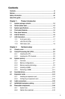
Contents Contents...iii Notices...vii Safety information viii About this guide ix Chapter 1: Product introduction 1.1 System package contents 1-2 1.2 Serial number label 1-2 1.3 System specifications 1-3 1.4 Front panel features 1-5 1.5 Rear panel features 1-5 1.6 Internal features 1-6 1.7 - Asus RS520-X5 PS8 | User Manual - Page 4
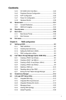
and updating your BIOS 5-2 5.1.1 Creating a bootable floppy disk 5-2 5.1.2 Updating the BIOS using the Phoenix Phlash16 Utility... 5-3 5.1.3 ASUS CrashFree BIOS 2 utility 5-4 5.2 BIOS setup program 5-6 5.2.1 BIOS menu screen 5-7 5.2.2 Menu bar 5-7 5.2.3 Legend bar 5-8 5.2.4 Menu items - Asus RS520-X5 PS8 | User Manual - Page 5
5.4.5 Peripheral Devices Configuration 5-24 5.4.6 ACPI Configuration 5-26 5.4.7 Power On Configuration 5-27 5.4.8 Hardware Monitor 5-28 5.5 Server menu 5-31 5.5.1 Console Redirection 5-31 5.5.2 DMI Event Logging 5-33 5.6 Security menu 5-34 5.7 Boot menu 5-36 5.7.1 Boot Device Priority 5-36 - Asus RS520-X5 PS8 | User Manual - Page 6
7-12 7.3 LAN driver installation 7-14 7.4 VGA driver installation 7-17 7.5 Management applications and utilities installation 7-19 7.5.1 Running the support DVD 7-19 7.5.2 Drivers menu 7-19 7.5.3 Management Software menu 7-20 7.5.4 Utilities menu 7-20 7.5.5 Contact information 7-20 vi - Asus RS520-X5 PS8 | User Manual - Page 7
, if not installed and used in accordance with manufacturer's instructions, may cause harmful interference to radio communications. However, there for help. WARNING! The use of shielded cables for connection of the monitor to the graphics card is required to assure compliance with FCC regulations. - Asus RS520-X5 PS8 | User Manual - Page 8
to fix it by yourself. Contact a qualified service technician or your dealer. Operation Safety • Any operating the server, carefully read all the manuals included with the server package. • Before used batteries according to the manufacturer's instructions. CD-ROM Drive Safety Warning CLASS - Asus RS520-X5 PS8 | User Manual - Page 9
users with at least basic knowledge of configuring a server. Contents This guide contains the following parts: 1. Chapter 1: Product Introduction This chapter describes 7: Driver installation This chapter provides instructions for installing the necessary drivers for different system components. ix - Asus RS520-X5 PS8 | User Manual - Page 10
sources for additional information, and for product and software updates. 1. ASUS Server Web-based Management (ASWM) user guide This manual tells how to set up and use the proprietary ASUS server management utility. 2. ASUS websites The ASUS websites worldwide provide updated information for all - Asus RS520-X5 PS8 | User Manual - Page 11
Product introduction Chapter 1 This chapter describes the general features of the chassis kit. It includes sections on front panel and rear panel specifications. ASUS RS520-X5/PS8 1- - Asus RS520-X5 PS8 | User Manual - Page 12
System Fans (80 x 38mm) 1 x Air Duct 1 x RS520-X5/PS8 User's Guide 1 x ASWM 2.0 User Guide 1 x RS520-X5/PS8 Support CD (including ASWM*) 1 x Bag of Screws 1 x AC Power Cable 1 x CA eTrust Anti-virus Software CD 1 x Slim-type optical drive 1 x Rackmount Kit *ASUS System Web-based Management If any - Asus RS520-X5 PS8 | User Manual - Page 13
) - Supports software RAID 0, 1, 0+1 & 5 LSI1068 PCI-X SAS controller: 8 x Serial Attached SCSI (SAS) channels (8 devices) with RAID 0, RAID 1, and RAID 1E configuration Zero-Channel RAID (colored green) 8 x Hot-swap 3.5" SAS/SATA HDD Bays (continued on the next page) ASUS RS520-X5/PS8 1-3 - Asus RS520-X5 PS8 | User Manual - Page 14
Storage FDD / CD / DVD Onboard I/O OS Support Anti-virus Software Management Solution Dimension (HH x WW x DD) SuSE® Linux Enterprise Server 10.0 32 / 64-bit CA® eTrust™ 7.1 anti-virus software (Optional) ASUS ASWM 2.0 615mm x 444mm x 87mm 12.5 Kg 500W 80+ Single Power Supply Operation - Asus RS520-X5 PS8 | User Manual - Page 15
LAN port2 LAN port1 VGA port Serial port USB ports PS/2 keyboard port PS/2 mouse port Power supply switch Power cord connector Power supply fan ASUS RS520-X5/PS8 1-5 - Asus RS520-X5 PS8 | User Manual - Page 16
1.6 Internal features The barebone server includes the basic components as shown. 1. ASUS DSBV-DX/SAS-SYS server board 2 2. Power supply 1 3. Power panel if you need to use a floppy disk. • Only ASUS CD/DVD-ROMs fit the optical drive bay. *WARNING HAZARDOUS MOVING PARTS KEEP FINGERS - Asus RS520-X5 PS8 | User Manual - Page 17
ON No activity Read/write data into the HDD System is normal; no incoming event ASWM indicates a HW monitor event Normal status Location switch is pressed (Press the location switch again to turn off) 10 Mbps connection ORANGE 100 Mbps connection GREEN 1 Gbps connection ASUS RS520-X5/PS8 1-7 - Asus RS520-X5 PS8 | User Manual - Page 18
1.7.3 HDD status LED HDD status LED SATA HDD LED Description GREEN This installed Serial ATA HDD is in good condition OFF HDD failure or no HDD is installed 1-8 Chapter 1: Product introduction - Asus RS520-X5 PS8 | User Manual - Page 19
Hardware setup Chapter 2 This chapter lists the hardware setup procedures that you have to perform when installing or removing system components. ASUS RS520-X5/PS8 2- - Asus RS520-X5 PS8 | User Manual - Page 20
2.1 Chassis cover Removing the rear cover 1. Loosen the two thumbscrews on the rear panel to release the rear cover from the chassis. Thumbscrews 2. Firmly hold the cover and slide it toward the rear panel for about half an inch until it is disengaged from the chassis. 1/2 inch distance 3. Lift the - Asus RS520-X5 PS8 | User Manual - Page 21
. • Your boxed Intel® Xeon® LGA771 processor package should come with installation instructions for the CPU and heatsink. If the instructions in this section do not match the CPU documentation, follow the latter. • is facing towards you and the load lever is on your left. ASUS RS520-X5/PS8 2-3 - Asus RS520-X5 PS8 | User Manual - Page 22
2. Press the load lever with your thumb (A), then move it to the left (B) until it is released from the retention tab. Retention tab A Load lever PnP cap B This side of the socket box should face you. To prevent damage to the socket pins, do not remove the PnP cap unless you are installing a - Asus RS520-X5 PS8 | User Manual - Page 23
The CPU fits in only one correct orientation. DO NOT force the CPU into the socket to prevent bending the connectors on the socket and damaging the CPU! A 6. Close the load plate (A), then push the load lever (B) until it snaps into the retention tab. B ASUS RS520-X5/PS8 2-5 - Asus RS520-X5 PS8 | User Manual - Page 24
2.2.2 Installing the CPU heatsink To install the CPU heatsink: 1. Carefully place the heatsink on top of the installed CPU. 2. Twist each of the four screws with a Philips (cross) screwdriver just enough to attach the heatsink to the motherboard. When the four screws are attached, tighten them one - Asus RS520-X5 PS8 | User Manual - Page 25
Vendors List on the ASUS web site. • This motherboard does not support memory modules made up of 128 Mb chips x16 memory modules. • If you are installing only one memory module, install into the white socket labeled DIMM_00. Installing into any other socket will not work. ASUS RS520-X5/PS8 2-7 - Asus RS520-X5 PS8 | User Manual - Page 26
Rank population DIMM 12 DIMM 11 DIMM 10 DIMM 02 DIMM 01 DIMM 00 MCH Slot 2 Slot 1 Slot 0 Slot 2 Slot 1 Slot 0 Channel Ch:0 Ch:1 DIMM installation reference table No. of DIMMs Slot/s to use 1 DIMM_00 2 DIMM_00, DIMM_10 4 DIMM_00, DIMM_01, DIMM_10, DIMM_11 6 DIMM_00, DIMM_01, - Asus RS520-X5 PS8 | User Manual - Page 27
sized rank to a larger sized one. • A DIMM can contain only one or two ranks. To support sparing function, a DIMM channel should contain at least two ranks. • When sparing function is enabled, the /2 Ranks) Rank 0 Rank 1 (1024 MB) (1024 MB) V V 1024 MB 1024 MB 2048 MB ASUS RS520-X5/PS8 2-9 - Asus RS520-X5 PS8 | User Manual - Page 28
Two DIMM per channel (Dual ranks) Sparing Memory space Sparing Memory space Total Memory Channel 0 DIMM_00 (1024MB/2 Ranks) Rank 0 Rank 1 (512 MB) (512 MB) Channel 1 DIMM_10 (1024MB/2 Ranks) Rank 0 Rank 1 (512 MB) (512 MB) 512 MB 512 MB 512 MB 512 MB DIMM_01 (2048MB/2 Ranks) DIMM_11 - Asus RS520-X5 PS8 | User Manual - Page 29
a DIMM: 1 1. Simultaneously press the retaining 2 clips outward to unlock the DIMM. Support the DIMM lightly with your fingers when pressing the retaining clips. The DIMM might get damaged when it flips out with extra force. 1 2. Remove the DIMM from the socket. ASUS RS520-X5/PS8 2-11 - Asus RS520-X5 PS8 | User Manual - Page 30
2.4 Hard disk drives The system supports eight hot-swap SATAII/SAS hard disk drives. The hard disk drive installed on the drive tray connects to the motherboard SATAII/SAS ports via - Asus RS520-X5 PS8 | User Manual - Page 31
6 if you wish to install a second SATAII/SAS drive. 8. Refer to section 2.7 SATAII/SAS backplane cabling for information on the SATAII/SAS backplane cable connections. ASUS RS520-X5/PS8 2-13 - Asus RS520-X5 PS8 | User Manual - Page 32
2.5 Expansion cards 2.5.1 Installing an expansion card The barebone server comes with two PCI-E expansion slots, allowing you to install half-height expansion cards. Ensure to unplug the power cord before installing or removing expansion cards. Failure to do so may cause severe damage to the - Asus RS520-X5 PS8 | User Manual - Page 33
on BIOS setup. 2. Assign an IRQ to the card. Refer to the following tables. 3. Install the software drivers for the expansion card. Standard interrupt assignments IRQ Priority Standard Function 0 1 1 2 2 - are usually available for ISA or PCI devices. ASUS RS520-X5/PS8 2-15 - Asus RS520-X5 PS8 | User Manual - Page 34
2.6 Cable connections • The bundled system cables are pre-connected before shipment. You do not need to disconnect these cables unless you will remove pre‑installed components to install additional devices. • Refer to Chapter 4 for detailed information on the connectors. 30.5cm (12in) PS/2 T: - Asus RS520-X5 PS8 | User Manual - Page 35
2.7 SATAII/SAS backplane cabling A SATAII/SAS backplane comes pre-installed in the RS520-X5/PS8. Front side The front side of the SATAII/SAS backplane faces the front panel when connectors and SATAII/SAS interfaces for the motherboard Serial ATA connectors or the SAS card. ASUS RS520-X5/PS8 2-17 - Asus RS520-X5 PS8 | User Manual - Page 36
2.8 Removable components You may need to remove previously installed system components when installing or removing system devices, or when you need to replace defective components. This section tells how to remove the following components: 1. System fans 2. Optical drive 2.8.1 System fans To - Asus RS520-X5 PS8 | User Manual - Page 37
drive: 1. Locate the optical drive eject latch at the rear side. 2. Press the latch leftward, and push the slim optical drive toward the front panel. ASUS RS520-X5/PS8 2-19 - Asus RS520-X5 PS8 | User Manual - Page 38
2-20 Chapter 2: Hardware setup - Asus RS520-X5 PS8 | User Manual - Page 39
Installation options Chapter 3 This chapter describes how to install the optional components and devices into the barebone server. ASUS RS520-X5/PS8 2- - Asus RS520-X5 PS8 | User Manual - Page 40
3.1 Rackmount rail kit items (optional) Your rackmount rail kit package contains: • two pair of server rails (for the server) • two pairs of rack rails (for the rack) • Nut-and-bolt type screws Rack rails Nuts and screws Front end Rear end 3-2 Chapter 3: Installation options - Asus RS520-X5 PS8 | User Manual - Page 41
to the side of the chassis with two screws. 4. Repeat steps 1 to 3 to attach the second server rail to the other side of the chassis. ASUS RS520-X5/PS8 3-3 - Asus RS520-X5 PS8 | User Manual - Page 42
3.3 Attaching the rack rails To attach the rack rails: 1. Select two units of space (2U) on the rack where you want to install the barebone server. 2. Install the nuts on the holes of the 2U space on the rack front. 3. Install the nuts on the holes of the 2U space on the corresponding rack rear. 4. - Asus RS520-X5 PS8 | User Manual - Page 43
Motherboard info Chapter 4 This chapter includes the motherboard layout, and brief descriptions of the jumpers and internal connectors. ASUS RS520-X5/PS8 3- 4-1 - Asus RS520-X5 PS8 | User Manual - Page 44
4.1 Motherboard layouts 4-2 Chapter 4: Motherboard information - Asus RS520-X5 PS8 | User Manual - Page 45
. System panel connector (20-1 pin PANEL1) 15. Auxiliary panel connector (20-pin AUX_PANEL1) Page 4-8 4-8 4-9 4-9 4-10 4-10 4-11 4-11 4-12 4-12 4-13 4-14 4-14 4-15 4-16 ASUS RS520-X5/PS8 4-3 - Asus RS520-X5 PS8 | User Manual - Page 46
4.2 Jumpers 1. Clear RTC RAM (CLRTC1) This jumper allows you to clear the Real Time Clock (RTC) RAM in CMOS. You can clear the CMOS memory of date, time, and system setup parameters by erasing the CMOS RTC RAM data. The onboard button cell battery powers the RAM data in CMOS, which include system - Asus RS520-X5 PS8 | User Manual - Page 47
. 3. VGA controller setting (3-pin VGA_EN1) These jumpers allow you to enable or disable the onboard VGA controller. Set to pins 1-2 to activate the VGA feature. ASUS RS520-X5/PS8 4-5 - Asus RS520-X5 PS8 | User Manual - Page 48
4. LAN controller setting (3-pin LAN_EN1) This jumper allows you to enable or disable the onboard Intel® 82563EB Gigabit LAN controller. Set to pins 1-2 to activate the Gigabit LAN feature. 5. Fan control setting (3-pin FAN_SEL1) This jumper allows you to switch for fan pin selection Set to pins - Asus RS520-X5 PS8 | User Manual - Page 49
floppy disk then turn on the system to update the BIOS. 4. Shut down the system. 5. Set the jumper back to pins 1-2. 6. Turn on the system. ASUS RS520-X5/PS8 4-7 - Asus RS520-X5 PS8 | User Manual - Page 50
4.3 Internal connectors 1. Floppy disk drive connector (34-1 pin FLOPPY1) This connector is for the provided floppy disk drive (FDD) signal cable. Insert one end of the cable to this connector, then connect the other end to the signal connector at the back of the floppy disk drive. Pin 5 on the - Asus RS520-X5 PS8 | User Manual - Page 51
disk activity LED connector (4-pin HDLED1) This connector is used to connect to a hard disk drive active LED connector on the SCSI or RAID card. ASUS RS520-X5/PS8 4-9 - Asus RS520-X5 PS8 | User Manual - Page 52
This motherboard comes with eight blue Serial Attached SCSI (SAS) connectors, the next-generation storage technology that supports both Serial Attached SCSI and Serial ATA (SATA). Each connector supports one device. To connect the SAS cable: Plug in the SAS cable to the SAS1-8 connector until - Asus RS520-X5 PS8 | User Manual - Page 53
opening at the back of the system chassis. This USB connector complies with USB 2.0 specification that supports up to 480 Mbps connection speed. The USB port module is purchased separately. 8. Serial port system chassis. The serial port module is purchased separately. ASUS RS520-X5/PS8 4-11 - Asus RS520-X5 PS8 | User Manual - Page 54
9. CPU and system fan connectors (4-pin CPU_FAN1/2, REAR_FAN1/2, FRNT_FAN1/2/3/4, FBD_FAN1) The fan connectors support cooling fans of 350 mA ~ 740 mA (8.88 W max.) or a total of 3.15 A ~ 6.66 A (53.28 W max.) at +12V. Connect the fan cables to the - Asus RS520-X5 PS8 | User Manual - Page 55
or may not boot up if the power is inadequate. • You must install a PSU with a higher power rating if you intend to install additional devices. ASUS RS520-X5/PS8 4-13 - Asus RS520-X5 PS8 | User Manual - Page 56
12. Parallel port connector (26-1 pin LPT1) This connector is for a parallel port. Connect the parallel port module cable to this connector, then install the module to a slot opening at the back of the system chassis. 13. Serial General Purpose Input/Output connector (2x4 pin SGPIO2) This connector - Asus RS520-X5 PS8 | User Manual - Page 57
connector (20-pin PANEL1) This connector supports several chassis-mounted functions. The system panel message LED. The message LED is controlled by Hardware monitor to indicate an abnormal event occurance. 3. System warning speaker (Orange 4-pin SPEAKER) off the system power. ASUS RS520-X5/PS8 4-15 - Asus RS520-X5 PS8 | User Manual - Page 58
microswitch. When you remove any chassis component, the sensor triggers and sends a high-level signal to these leads to record a chassis intrusion event. The default setting is short CASEOPEN and GND pin by jumper cap to disable the function. 4. Locator LED (2-pin LOCATORLED1 and 2-pin LOCATORLED2 - Asus RS520-X5 PS8 | User Manual - Page 59
Chapter 5 This chapter tells how to change the system settings through the BIOS Setup menus. Detailed descriptions of the BIOS parameters are also provided. BIOS setup ASUS RS520-X5/PS8 3- - Asus RS520-X5 PS8 | User Manual - Page 60
motherboard BIOS file to a bootable floppy disk in case you need to restore the BIOS in the future. Copy the original motherboard BIOS using the ASUS Update or Phoenix Phlash16 BIOS utilities. Refer to page 5-3 for details. • Set the Floppy A item in Main menu to [Disabled] when using a USB floppy - Asus RS520-X5 PS8 | User Manual - Page 61
Utility. Follow these instructions to update the BIOS using this utility. 1. Download the latest BIOS file from the ASUS web site. Rename Copy the Phoenix Phlash16 (phlash16.exe) utility from the Software folder of the support CD to the floppy disk with the latest BIOS file. ASUS RS520-X5/PS8 5-3 - Asus RS520-X5 PS8 | User Manual - Page 62
BIOS 2 utility The ASUS CrashFree BIOS 2 is an auto recovery tool that allows you to restore the BIOS the recovery diskette: 1. Insert a floppy disk to the floppy disk drive, then boot from the support CD. The screen will show several options. 2. Select the item "Create the emergent BIOS Recovery - Asus RS520-X5 PS8 | User Manual - Page 63
for more than four seconds to turn off the system. The recovered BIOS may not be the latest BIOS version for this motherboard. Visit the ASUS website (www.asus.com) to download the latest BIOS file. ASUS RS520-X5/PS8 5-5 - Asus RS520-X5 PS8 | User Manual - Page 64
5.2 BIOS setup program This motherboard supports a programmable Low-Pin Count (LPC) chip that you can update using the provided may not exactly match what you see on your screen. • Visit the ASUS website (www.asus.com) to download the latest BIOS file for this motherboard. 5-6 Chapter 5: BIOS setup - Asus RS520-X5 PS8 | User Manual - Page 65
settings To select an item on the menu bar, press the right or left arrow key on the keyboard until the desired item is highlighted. ASUS RS520-X5/PS8 5-7 - Asus RS520-X5 PS8 | User Manual - Page 66
5.2.3 Legend bar At the bottom of the Setup screen is a legend bar. The keys in the legend bar allow you to navigate through the various setup menus. The following table lists the keys found in the legend bar with their corresponding functions. Navigation Key Function - Asus RS520-X5 PS8 | User Manual - Page 67
F10 Save and Exit Pop-up menu 5.2.8 General help At the top right corner of the menu screen is a brief description of the selected item. ASUS RS520-X5/PS8 5-9 - Asus RS520-X5 PS8 | User Manual - Page 68
5.3 Main menu When you enter the BIOS Setup program, the Main menu screen appears, giving you an overview of the basic system information. Refer to section 5.2.1 BIOS menu screen for information on the menu screen items and how to navigate through them. Main Advanced System Date System Time - Asus RS520-X5 PS8 | User Manual - Page 69
Enter Select Sub-Menu F10 Save and Exit Parallel ATA [Enabled] Allows you to enable or disable the parallel ATA function. Configuration options: [Disabled] [Enabled] ASUS RS520-X5/PS8 5-11 - Asus RS520-X5 PS8 | User Manual - Page 70
set this item to Compatible Mode, Serial ATA and Parallel ATA devices are auto‑detected and placed in legacy mode. Set this item to [Compatible] if ] or [Compatible] and disable ACHI/RAID mode, Intel 6321ESB can only support maximum four hard disk drives. If you set the SATA Controller Mode Option - Asus RS520-X5 PS8 | User Manual - Page 71
the LBA mode if the device supports this mode, and if the device was not previously formatted with LBA mode disabled. Configuration options: [Disabled] [Enabled] 32-Bit I/O: [Disabled] Enables or disables 32-bit data transfer. Configuration options: [Disabled] [Enabled] ASUS RS520-X5/PS8 5-13 - Asus RS520-X5 PS8 | User Manual - Page 72
to [Mode 0-5], the UDMA capability allows improved transfer speeds and data integrity for supported IDE devices. Configuration options: [Disabled] [Mode 0] [Mode 1] [Mode 2] Information Model Name Model ID DSBV-DX/SAS 8051A0 ASUS-BIOS Version Date 1009 09/05/2008 Processor Information System - Asus RS520-X5 PS8 | User Manual - Page 73
Enter Select Sub-Menu F10 Save and Exit System Memory Information Displays the auto-detected system memory information. Main PhoenixBIOS Setup Utility System Memory Information Speed : -/+ Change Values F9 Setup Defaults Enter Select Sub-Menu F10 Save and Exit ASUS RS520-X5/PS8 5-15 - Asus RS520-X5 PS8 | User Manual - Page 74
Peripheral Devices Configuration ACPI Configuration Power On Configuration Hardware Monitor Exit Item Specific Help Options for CPU F1 display the following items: Advanced Processor Options Discrete MTRR Allocation Intel EIST support: [Disabled] [Disabled] F1:Help ESC: Exit ↑↓ : Select Item - Asus RS520-X5 PS8 | User Manual - Page 75
: [Enabled] [Disabled] Set Max Ext CPUID = 3 [Disabled] Enable this item to boot legacy operating systems that cannot support CPUs with extended CPUID functions. Configuration options: [Disabled] [Enabled] Echo TPR [Disabled] Configuration options: [Enabled] [Disabled] ASUS RS520-X5/PS8 5-17 - Asus RS520-X5 PS8 | User Manual - Page 76
this item allows the CPU P state to dynamically change based on system loading. Configuration options: [Disabled] [Enabled] • The appearance of the Intel EIST support item depends on the CPU SKU. • Items above with * mark are for technical personnel to debug only. If you install a 5200/5400 series - Asus RS520-X5 PS8 | User Manual - Page 77
enabled, this item allows the CPU P state to dynamically change based on system loading. Configuration options: [Disabled] [Enabled] • The appearance of the Intel EIST support item depends on the CPU SKU. • Items above with * mark are for technical personnel to debug only. ASUS RS520-X5/PS8 5-19 - Asus RS520-X5 PS8 | User Manual - Page 78
5.4.2 Chipset Configuration This menu shows the chipset configuration settings. Select an item then press to display a pop-up menu with the configuration options. Advanced PhoenixBIOS Setup Utility Chipset Configuration Crystal Beach Configure Enable SERR signal condition Demand Scrub - Asus RS520-X5 PS8 | User Manual - Page 79
throttling control. Configuration options: [Open Loop] [Closed Loop] [ASUS MemCool FAN] [Disabled] Set this item to [ASUS MemCool FAN] for a better fan management. Open Loop Type [User Allows yout to select the Air Flow value. Configuration options: [1.0] [1.5]~[4.5] [5.0] ASUS RS520-X5/PS8 5-21 - Asus RS520-X5 PS8 | User Manual - Page 80
5.4.3 PCI Configuration This menu shows the PCI configuration settings. Select an item then press to display the configuration options. Advanced PhoenixBIOS Setup Utility PCI Configuration Reset Configuration Data: Plug & Play OS Palette Snooping PCIEX1 Slot PCIEX2 Slot PCI3 Slot - Asus RS520-X5 PS8 | User Manual - Page 81
Setup Utility ICH USB Control Sub-Menu USB Function USB 2.0 Controller Legacy USB Support: [Enabled] [Enabled] [Enabled] Item Specific Help Enable USB host controller. USB device is detected, the legacy USB support is disabled. Configuration options: [Disabled] [Enabled] ASUS RS520-X5/PS8 5-23 - Asus RS520-X5 PS8 | User Manual - Page 82
Defaults Enter Select Sub-Menu F10 Save and Exit COM1 port [Enabled] Allows you to configure COM1 port. Configuration options: [Disabled] [Enabled] [Auto] Base I/O address [3F8] Allows you to select the base I/O address for COM1 port. Configuration options: [3F8] [2F8] [3E8] [2E8] Interrupt [IRQ - Asus RS520-X5 PS8 | User Manual - Page 83
[Enabled] Allows you to configure the parallel port. Configuration options: [Disabled] [Enabled] [Auto] Base I/O address [378] Allows you to select the base I/O address for the parallel configure the floppy disk controller. Configuration options: [Disabled] [Enabled] [Auto] ASUS RS520-X5/PS8 5-25 - Asus RS520-X5 PS8 | User Manual - Page 84
press to display the configuration options. Advanced PhoenixBIOS Setup Utility ACPI Configuration ACPI Version Features Headless Mode ACPI EMS Support [ACPI v1.0] [Disabled] [Disabled] Item Specific Help Enable RSDP pointers to 64-bit Fixed System Description Tables. F1 Help ESC - Asus RS520-X5 PS8 | User Manual - Page 85
] Allows you to enable or disable the PME and onboard LAN to generate a wake-up event. Configuration options: [Disabled] [Enabled] Power On By RTC Alarm [Disabled] Allows you to enable or disable RTC to generate a wake-up event. Configuration options: [Disabled] [Enabled] ASUS RS520-X5/PS8 5-27 - Asus RS520-X5 PS8 | User Manual - Page 86
the left/right arrow key or press to move to the next field. 3. Press when done. 5.4.8 Hardware Monitor This menu shows the hardware monitor configuration settings. Select an item then press to display the configuration options. The following screens appear when you install - Asus RS520-X5 PS8 | User Manual - Page 87
Intel® 5200 and 5400 series CPU. Advanced PhoenixBIOS Setup Utility Hardware Monitor CPU1 Temperature CPU2 Temperature SYSTEM1 Temperature SYSTEM2 Temperature CPU_FAN1 Speed CPU_FAN2 Speed Setup Defaults ESC Exit →← Select Menu Enter Select Sub-Menu F10 Save and Exit ASUS RS520-X5/PS8 5-29 - Asus RS520-X5 PS8 | User Manual - Page 88
down to display more items: Advanced PhoenixBIOS Setup Utility Hardware Monitor SYSTEM1 Target Temperature SYSTEM2 Target Temperature [60 oC] [60 CPU_FAN1/2 Speed, FRN_FAN1/2/3/4 Speed, REAR_FAN1/2 Speed These fields show the auto-detected values and are not user-configurable. If no CPU or fan - Asus RS520-X5 PS8 | User Manual - Page 89
the server features. Main Advanced Console Redirection DMI Event Logging PhoenixBIOS Setup Utility Server Security Boot Exit Rate Console Type Flow Control Continue C.R. after POST: # of video pages to support: [Onboard COM1 port] [57.6K] [VT-UTF8] [None] [On port] ASUS RS520-X5/PS8 5-31 - Asus RS520-X5 PS8 | User Manual - Page 90
to [On] if you want console redirection to continue after the operating system has loaded. Configuration options: [Off] [On] # of video pages to support [1] Allows you to set the number of video pages to allocate for console redirection when the video hardware is not available. Press or to - Asus RS520-X5 PS8 | User Manual - Page 91
events. Configuration options: [Disabled] [Enabled] Mark DMI events as read [Enter] Press to mark all DMI events in the event log as read. Clear all DMI event logs [No] Allows you to keep or clear the DMI event log after rebooting. Configuration options: [No] [Yes] ASUS RS520-X5/PS8 5-33 - Asus RS520-X5 PS8 | User Manual - Page 92
5.6 Security menu Main Advanced PhoenixBIOS Setup Utility Server Security Boot Supervisor Password Is: User Password Is: Set Supervisor Password Set User Password Password Check Password Lock Mode Removable Device Boot Flash Write Clear Clear [Enter] [Enter] [Setup] [Disabled] [Enabled] [ - Asus RS520-X5 PS8 | User Manual - Page 93
battery. If you need to erase the CMOS RAM, refer to section "4.2 Jumpers" for instructions. Password Check [Setup] This field requires you to enter the password before entering the BIOS to write-protect the BIOS flash memory. Configuration options: [Disabled] [Enabled] ASUS RS520-X5/PS8 5-35 - Asus RS520-X5 PS8 | User Manual - Page 94
5.7 Boot menu Main Advanced PhoenixBIOS Setup Utility Server Security Boot Boot Device Priority Boot Features Exit Item Specific Help Specify the boot priority sequence of all boot devices. F1 Help ESC Exit ↑↓ Select Item →← Select Menu -/+ Change Values F9 Setup Defaults Enter - Asus RS520-X5 PS8 | User Manual - Page 95
. Configuration options: [Auto] [On] [Off] PS/2 Mouse [Auto Detect] Allows you to enable or disable support for PS/2 mouse. Configuration options: [Disabled] [Enabled] [Auto Detect] Summary screen: to be pressed when error occurs. Configuration options: [Disabled] [Enabled] ASUS RS520-X5/PS8 5-37 - Asus RS520-X5 PS8 | User Manual - Page 96
SETUP prompt [Enabled] When this item is set to [Enabled], the system displays the message "Press DEL to run Setup" during POST. Configuration options: [Disabled] [Enabled] Interrupt 19 Capture [Enabled] When set to [Enabled], this function allows the option ROMs to trap Interrupt 19. Configuration - Asus RS520-X5 PS8 | User Manual - Page 97
to load the default values. • select [No], then press , or simply press , to cancel the command and return to the Exit menu. ASUS RS520-X5/PS8 5-39 - Asus RS520-X5 PS8 | User Manual - Page 98
5-40 Chapter 5: BIOS setup - Asus RS520-X5 PS8 | User Manual - Page 99
RAID configuration Chapter 6 This chapter provides instructions for setting up, creating and configuring RAID sets using the available utilities. ASUS RS520-X5/PS8 3- - Asus RS520-X5 PS8 | User Manual - Page 100
to a second drive. If one drive fails, the disk array management software directs all applications to the surviving drive as it contains a complete copy created RAID set, copy first the RAID driver from the support CD to a floppy disk before you install an operating system to the selected hard - Asus RS520-X5 PS8 | User Manual - Page 101
6321ESB Southbridge. You may use the LSI1068 SAS Configuration Utility if you installed SAS hard disk drives to the mini-SAS connector(s) supported by the LSI1068 PCI-X SAS controller. Refer to the succeeding sections for details on how to use each RAID configuration utility. ASUS RS520-X5/PS8 6-3 - Asus RS520-X5 PS8 | User Manual - Page 102
in this section are for reference only and may not exactly match the items on your screen due to the controller version difference. The utility supports maxium four hard disk drives for RAID configurration. 6-4 Chapter 6: RAID configuration - Asus RS520-X5 PS8 | User Manual - Page 103
the up/down arrow key to highlight a drive, then press to select. A small triangle marks the selected drive. Press after completing your selection. ASUS RS520-X5/PS8 6-5 - Asus RS520-X5 PS8 | User Manual - Page 104
6. Use the up/down arrow key to select the stripe size for the RAID 0 array, then press . The available stripe size values range from 4 KB to 128 KB. The default stripe size is 128 KB. A lower stripe size is recommended for server systems. A higher stripe size is recommended for multimedia - Asus RS520-X5 PS8 | User Manual - Page 105
up/down arrow key to select RAID 1 (Mirror), then press . 4. Follow steps 4 to 5 and 7 to 9 of the previous section to create the RAID 1 set. ASUS RS520-X5/PS8 6-7 - Asus RS520-X5 PS8 | User Manual - Page 106
6.2.3 Creating a RAID 10 set (Stripe + Mirror) To create a RAID 10 set: 1. From the utility main menu, select 1. Create RAID Volume, then press . This screen appears. Intel(R) Matrix Storage Manager option ROM v5.6.2.1002 ESB2 Copyright(C) 2003-06 Intel Corporation. All Rights Reserved. [ - Asus RS520-X5 PS8 | User Manual - Page 107
the up/down arrow key to select RAID5, then press . 4. Follow steps 4 to 9 of section 6.2.1 Creating a RAID 0 set (striped) to create the RAID 5 set. ASUS RS520-X5/PS8 6-9 - Asus RS520-X5 PS8 | User Manual - Page 108
6.2.5 Deleting a RAID set Take caution when deleting a RAID set. You will lose all data on the hard disk drives when you delete a RAID set. To delete a RAID set: 1. From the utility main menu, select 2. Delete RAID Volume, then press to display this screen. Intel(R) Matrix Storage - Asus RS520-X5 PS8 | User Manual - Page 109
. This window appears. [ CONFIRM EXIT ] Are you sure you want to exit? (Y/N): 2. Press to exit or press to return to the utility main menu. ASUS RS520-X5/PS8 6-11 - Asus RS520-X5 PS8 | User Manual - Page 110
You may also create a RAID set(s) in Windows® operating environment using the Global Array Manager (GAM) application. The GAM application is available from the motherboard support CD. Refer to the GAM user guide in the motherboard support CD for details. 6-12 Chapter 6: RAID configuration - Asus RS520-X5 PS8 | User Manual - Page 111
that allows you to allows you to create the following RAID set(s) from SAS hard disk drives supported by the LSI1068 PCI-X SAS controller: • RAID 1 (Integrated Mirroring) • RAID 1E (Integrated 2000-2007 LSI Corporation. Press Ctrl-C to start LSI Corp Configuration Utility... ASUS RS520-X5/PS8 6-13 - Asus RS520-X5 PS8 | User Manual - Page 112
.08.07) Adapter Properties -- SAS1068 Adapter PCI Slot PCI Address(Bus/Dev/Func) MPT Firmware Revision SAS Address NVIDIA Version Status Boot Order Boot Support SAS1068 00 05.03.00 1.15.00.00.IR 500E0180:60831008 25.02 Disabled 0 (Enabled OS only) RAID Properties SAS Topology Advanced Adapter - Asus RS520-X5 PS8 | User Manual - Page 113
on the primary drive. • The disk has been selected as the Hot Spare for the RAID array. • The disk is already part of another array. ASUS RS520-X5/PS8 6-15 - Asus RS520-X5 PS8 | User Manual - Page 114
7. A confirmation screen appears. Press to keep existing data on the first disk. If you choose this option, data on the first disk will be mirrored on the second disk that you will add to the volume later. Ensure the data you want to mirror is on the first disk. Press to overwrite any data - Asus RS520-X5 PS8 | User Manual - Page 115
PCI Slot PCI Address(Bus/Dev/Func) MPT Firmware Revision SAS Address NVIDIA Version Status Boot Order Boot Support RAID Properties SAS1068 00 05.03.00 1.15.00.00-IR 500E0180:60831008 25.02 Disabled 0 ! Esc = Exit Menu F1/Shift+1 = Help Enter = Choose array type to create ASUS RS520-X5/PS8 6-17 - Asus RS520-X5 PS8 | User Manual - Page 116
3. The Create New Array screen shows the disks you can add to make up the IME volume. Integrated Mirroring Enhanced (IME) supports three to eight disks, or seven mirrored disks plus a hot spare disk. Use the arrow key to select a disk, then move the cursor to the - Asus RS520-X5 PS8 | User Manual - Page 117
Address NVIDIA Version Status Boot Order Boot Support RAID Properties SAS Topology SAS1068 00 05.03.00 1.15.00.00-IR 500E0180:60831008 25.02 Disabled 0 (Enabled OS only) Advanced Adapter Properties Esc = Exit Menu F1/Shift+1 = Help Enter = Select Item -/+ = Change Item ASUS RS520-X5/PS8 6-19 - Asus RS520-X5 PS8 | User Manual - Page 118
4. The Select New Array Type screen apprears. Use the arrow keys to select Create IS Volume, then press . LSI Logic Config Utility v6.18.00.00 (2007.08.07) Select New Array Type -- SAS1068 Create IM Volume Create Integrated Mirror Array of 2 disks plus an optional hot spare. Data - Asus RS520-X5 PS8 | User Manual - Page 119
Reboot 9. The utility creates the array. LSI Logic Config Utility v6.18.00.00 (2007.08.07) Processing...may take up 1 minute Creating RAID array ASUS RS520-X5/PS8 6-21 - Asus RS520-X5 PS8 | User Manual - Page 120
2007.08.07) Adapter Properties -- SAS1068 Adapter PCI Slot PCI Address(Bus/Dev/Func) MPT Firmware Revision SAS Address NVIDIA Version Status Boot Order Boot Support RAID Properties SAS1068 00 05.03.00 1.15.00.00-IR 500E0180:60831008 25.02 Disabled 0 (Enabled OS only) SAS Topology Advanced Adapter - Asus RS520-X5 PS8 | User Manual - Page 121
No 34331 3 SEAGATE ST373454SS 0003 Yes NO Ok No 34331 Esc = Exit Menu F1/Shift+1 = Help Enter=Select Item Alt+N=Next Array C = Create an array ASUS RS520-X5/PS8 6-23 - Asus RS520-X5 PS8 | User Manual - Page 122
Managing hot spares You may configure one disk as a global hot spare to protect critical data on the IM/ IME volume(s). You may create the hot spare disk at the same time you create the IM/IME volume. Refer to this section when adding a hot spare disk on an existing volume. If a disk on an IM/IME - Asus RS520-X5 PS8 | User Manual - Page 123
Hot Spare Synnchronize Array Activate Array Delete Array Esc = Exit Menu Enter = Select Item F1/Shift+1 = Help 3. Press to begin the synchronization, or to cancel. ASUS RS520-X5/PS8 6-25 - Asus RS520-X5 PS8 | User Manual - Page 124
Activating an array If an array is removed from one controller/computer or moved to another, the array is considered inactive. When you add the array back to the system, you may reactivate the array. To activate the array: 1. From the Manage Array screen, select Activate Array, then press . - Asus RS520-X5 PS8 | User Manual - Page 125
PCI Slot PCI Address(Bus/Dev/Func) MPT Firmware Revision SAS Address NVIDIA Version Status Boot Order Boot Support RAID Properties SAS1068 00 05.03.00 1.15.00.00-IR 500E0180:60831008 25.02 Disabled 0 (Enabled SAS SAS Esc=Exit F1=Help Alt+D=Device Properties Alt+N=More Keys ASUS RS520-X5/PS8 6-27 - Asus RS520-X5 PS8 | User Manual - Page 126
CU, select an adapter from the Adapter List. 2. Select the SAS Topology option. The current topology is displayed. If the selection of a boot device is supported, the bottom of the screen lists the Alt+B option. This is the key for toggling the boot device. If a device is currently configured as the - Asus RS520-X5 PS8 | User Manual - Page 127
List Global Properties Pause When Boot Alert Displayed Boot Information Display Mode Support Interrupt Restore Defaults [No] [Display adapters & installed devices] [Hook interrupt, the Default] Esc = Exit Menu F1/Shift+1 = Help Allt+N = Adapter List -/+ = Change Item ASUS RS520-X5/PS8 6-29 - Asus RS520-X5 PS8 | User Manual - Page 128
v6.18.00.00 (2007.08.07) Adapter List Global Properties Pause When Boot Alert Displayed Boot Information Display Mode Support Interrupt Restore Defaults [No] [Display adapters & installed devices] [Hook interrupt, the Default] Esc = Exit Menu F1/Shift+1 = Help Allt+N = Adapter - Asus RS520-X5 PS8 | User Manual - Page 129
List Global Properties Pause When Boot Alert Displayed Boot Information Display Mode Support Interrupt Restore Defaults [No] [Display adapters & installed devices] [Hook interrupt, the Default] Esc = Exit Menu F1/Shift+1 = Help Allt+N = Adapter List -/+ = Change Item ASUS RS520-X5/PS8 6-31 - Asus RS520-X5 PS8 | User Manual - Page 130
6-32 Chapter 6: RAID configuration - Asus RS520-X5 PS8 | User Manual - Page 131
Driver installation Chapter 7 This chapter provides instructions for installing the necessary drivers for different system components. ASUS RS520-X5/PS8 - Asus RS520-X5 PS8 | User Manual - Page 132
the independent hard disk drive or bootable array. This part provides instructions on how to install the RAID controller drivers during OS installation. use another system to create the RAID driver disk from the system/motherboard support DVD or from the Internet. A floppy disk with the RAID driver - Asus RS520-X5 PS8 | User Manual - Page 133
SP1 64 bit Back Exit 6. Locate the RAID driver and place a blank, high-density floppy disk to the floppy disk drive. 7. Press . 8. Follow screen instructions to create the driver disk. ASUS RS520-X5/PS8 7-3 - Asus RS520-X5 PS8 | User Manual - Page 134
1. Start Windows®. 2. Place the motherboard support DVD into the optical drive. 3. Go to the Make Disk menu, and then select the type of RAID driver disk you want to create. 4. Insert a floppy disk into the floppy disk drive. 5. Follow succeeding screen instructions to complete the process. Write - Asus RS520-X5 PS8 | User Manual - Page 135
chosen to manually specify an adapter. Currently, Setup will load support for the support disks from a mass storage device manufacturer, or do not want to specify additional mass storage devices for use with Windows, press ENTER. S=Specify Additional Device ENTER=Continue F3=Exit ASUS RS520-X5/PS8 - Asus RS520-X5 PS8 | User Manual - Page 136
insert the disk labeled Manufacturer-supplied hardware support disk into Drive A: * Press ENTER proceeds with the OS installation. Follow screen instructions to continue. To an existing Windows® Server drive. 9. Select the option Install the software automatically (Recommended), and then click Next. - Asus RS520-X5 PS8 | User Manual - Page 137
Properties from the menu. 5. Click the Driver tab, and then click the Driver Details button to display the RAID controller drivers. 6. Click OK when finished. ASUS RS520-X5/PS8 7-7 - Asus RS520-X5 PS8 | User Manual - Page 138
Red Hat® Enterprise Linux OS To install the RAID controller driver when installing Red Hat® Enterprise Linux OS 1. Boot the system from the Red Hat® Installation DVD. 2. At the boot:, type linux dd , then press . - To install or upgrade in graphical mode, press the key. - To install - Asus RS520-X5 PS8 | User Manual - Page 139
RAID controller drivers, select No, then press . More Driver Disks? Do you wish to load any more driver disks? Yes No 7. Follow the screen instructions to continue the OS installation. ASUS RS520-X5/PS8 7-9 - Asus RS520-X5 PS8 | User Manual - Page 140
SUSE Linux OS To install the RAID controller driver when installing SUSE Linux Enterprise Server OS 1. Boot the system from the SUSE OS installation DVD. 2. Use the arrow keys to select Installation from the Boot Options menu. Boot from Hard Disk Installation Installation--ACPI Disabled Installation - Asus RS520-X5 PS8 | User Manual - Page 141
DV-516E sda: Disk, SEAGATE ST336754SS sdb: Disk, SEAGATE ST336754SS Other device OK Back The drivers for the RAID controller are installed to the system. ASUS RS520-X5/PS8 7-11 - Asus RS520-X5 PS8 | User Manual - Page 142
DVD to the optical drive. The support DVD automatically displays the Drivers menu if Autorun is enabled in your computer. 3. Click the item Intel Chipset Device Software from the menu. 4. The Intel(R) Chipset Device Software window appears. Follow the screen instructions to start installation. 7-12 - Asus RS520-X5 PS8 | User Manual - Page 143
5. Select Yes to accept the terms of the License Agreement and continue the process. 6. Read the Readme File Information and press Next to continue the installation. 7. After completing the installation, click Finish to complete the setup process. ASUS RS520-X5/PS8 7-13 - Asus RS520-X5 PS8 | User Manual - Page 144
instructions on how to install the Intel® Gigabit LAN controller drivers on a Windows® Server OS. To install the LAN controller drivers 1. Restart the computer, and then log on with Administrator privileges. 2. Insert the motherboard/system support the contents of the support DVD to locate the - Asus RS520-X5 PS8 | User Manual - Page 145
the license agreement and click Next to continue. 7. Click the Intel(R) PROSet for Windows Device Manager box, and then click Next to start the installation. ASUS RS520-X5/PS8 7-15 - Asus RS520-X5 PS8 | User Manual - Page 146
8. Follow the screen instructions to complete installation. 9. When finished, press Finish to continue. 7-16 Chapter 7: Driver installation - Asus RS520-X5 PS8 | User Manual - Page 147
privileges. 2. Insert the motherboard/system support DVD to the optical drive. The support DVD automatically displays the Drivers menu if Autorun is enabled in your computer. The Drivers menu if Autorun is enabled in your computer. 3. Click Next to start the installation. ASUS RS520-X5/PS8 7-17 - Asus RS520-X5 PS8 | User Manual - Page 148
4. When the installation completes, click Finish to restart your computer before using the program. 7-18 Chapter 7: Driver installation - Asus RS520-X5 PS8 | User Manual - Page 149
The contents of the support DVD are subject to change at any time without notice. Visit the ASUS website (www.asus.com) for updates. 7.5.1 Running the support DVD Place the support DVD to the optical display and driver options vary under different operating system versions. ASUS RS520-X5/PS8 7-19 - Asus RS520-X5 PS8 | User Manual - Page 150
and server monitoring applications. Click an item to install. 7.5.4 Utilities menu The Utilities menu displays the software applications and utilities that the motherboard supports. Click an item to install. 7.5.5 Contact information Click the Contact tab to display the ASUS contact information
-
 1
1 -
 2
2 -
 3
3 -
 4
4 -
 5
5 -
 6
6 -
 7
7 -
8
-
9
-
10
-
11
-
12
-
13
-
14
-
15
-
16
-
17
-
18
-
19
-
20
-
21
-
22
-
23
-
24
-
25
-
26
-
27
-
28
-
29
-
30
-
31
-
32
-
33
-
34
-
35
-
36
-
37
-
38
-
39
-
40
-
41
-
42
-
43
-
44
-
45
-
46
-
47
-
48
-
49
-
50
-
51
-
52
-
53
-
54
-
55
-
56
-
57
-
58
-
59
-
60
-
61
-
62
-
63
-
64
-
65
-
66
-
67
-
68
-
69
-
70
-
71
-
72
-
73
-
74
-
75
-
76
-
77
-
78
-
79
-
80
-
81
-
82
-
83
-
84
-
85
-
86
-
87
-
88
-
89
-
90
-
91
-
92
-
93
-
94
-
95
-
96
-
97
-
98
-
99
-
100
-
101
-
102
-
103
-
104
-
105
-
106
-
107
-
108
-
109
-
110
-
111
-
112
-
113
-
114
-
115
-
116
-
117
-
118
-
119
-
120
-
121
-
122
-
123
-
124
-
125
-
126
-
127
-
128
-
129
-
130
-
131
-
132
-
133
-
134
-
135
-
136
-
137
-
138
-
139
-
140
-
141
-
142
-
143
-
144
-
145
-
146
-
147
-
148
-
149
-
150
 |
 |

2U Rackmount Server
RS520-X5/PS8
User Guide