Asus T2-R T2-R User Manual
Asus T2-R - Terminator - Deluxe Manual
 |
UPC - 610839531141
View all Asus T2-R manuals
Add to My Manuals
Save this manual to your list of manuals |
Asus T2-R manual content summary:
- Asus T2-R | T2-R User Manual - Page 1
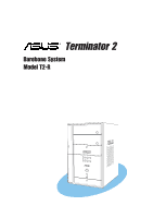
Terminator 2 Barebone System Model T2-R User Guide MODE - Asus T2-R | T2-R User Manual - Page 2
or translated into any language in any form or by any means, except documentation kept by the purchaser for backup purposes, without the express written permission of ASUSTeK COMPUTER INC. ("ASUS"). Product warranty or service will not be extended if: (1) the product is repaired, modified or altered - Asus T2-R | T2-R User Manual - Page 3
About this guide 8 System package contents 10 Chapter 1: System introduction power supply 24 2.5 Installing a CPU 25 2.5.1 Removing the CPU fan and heatsink assembly .... 25 2.5.2 CPU installation 26 2.5.3 Re-installing the CPU fan and heatsink assembly 27 2.6 Installing a DIMM 28 2.6.1 Memory - Asus T2-R | T2-R User Manual - Page 4
and driver ......... 59 3.6.4 Other support CD options 59 3.6.5 The Control Center utility 60 Chapter 4: Motherboard info 4.1 Introduction 72 4.2 Motherboard layout 72 4.3 Jumper 73 4.4 Internal connectors 74 Chapter 5: BIOS setup 5.1 Managing and updating your BIOS 82 5.1.1 Creating - Asus T2-R | T2-R User Manual - Page 5
Setup program 91 5.2.1 BIOS menu screen 92 5.2.2 Menu bar 92 5.2.3 Navigation keys 92 5.2.4 Menu items 93 5.2.5 Sub-menu items 93 5.2.6 Configuration fields 93 5.2.7 Pop-up window 93 5.2.8 Scroll bar 93 5.2.9 General help 93 5.3 Main menu 94 5.3.1 System Time 94 5.3.2 System Date 94 - Asus T2-R | T2-R User Manual - Page 6
. This equipment generates, uses and can radiate radio frequency energy and, if not installed and used in accordance with manufacturer's instructions, may cause harmful interference to radio communications. However, there is no guarantee that interference will not occur in a particular installation - Asus T2-R | T2-R User Manual - Page 7
system. • When adding or removing devices to or from the system, ensure that the power cables for the devices are unplugged before the signal cables are connected. • If the power supply • If you encounter technical problems with the product, contact a qualified service technician or your retailer. - Asus T2-R | T2-R User Manual - Page 8
on the ASUS Terminator 2 barebone system. Included in this guide are installation instructions and other information regarding the system. This guide is intended for experienced users and integrators with hardware knowledge of personal computers. How this guide is organized This guide contains the - Asus T2-R | T2-R User Manual - Page 9
task. IMPORTANT: Instructions that you MUST follow to complete a task. NOTE: Tips and additional information to help you complete a task. Where to find more information Refer to the following sources for additional information and for product and software updates. 1. ASUS websites The ASUS websites - Asus T2-R | T2-R User Manual - Page 10
Deluxe Deluxe Standard 1. ASUS Terminator 2 barebone system with • ASUS P4R8T motherboard • 3-in-1 PCI card* • Floppy disk drive • 7-in-1 storage card reader • FM radio module and radio antenna • LED panel • CPU fan and heatsink assembly 2. AC power cable 3. Support CD 4. User guide - Asus T2-R | T2-R User Manual - Page 11
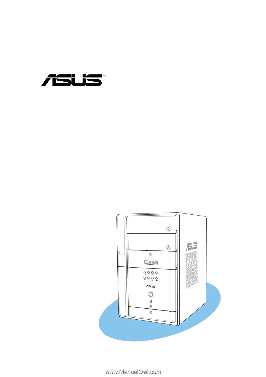
System introduction Chapter 1 This chapter gives a general description of the ASUS Terminator 2. The chapter lists the system features, including introduction on the front and rear panel, and internal components. MODE ASUS Terminator 2 barebone system - Asus T2-R | T2-R User Manual - Page 12
the ASUS Terminator 2! The ASUS Terminator 2 is an all-in-one barebone system with a versatile home entertainment feature. Delivered in a stylish mini-tower casing and powered by the ASUS P4R8T motherboard that supports Intel® Pentium® 4 processor with an 800MHz FSB, and up to 2GB system memory, the - Asus T2-R | T2-R User Manual - Page 13
button to put the Audio DJ function to CD mode. In Windows® mode, pressing this button shuts down, restarts, or puts the system in sleep mode (S3) depending on the OS setting. 12. Mode button. Press this button to switch from CD to FM radio mode or vice versa. ASUS Terminator 2 barebone system 13 - Asus T2-R | T2-R User Manual - Page 14
CD mode, selects the next audio track. In Radio mode, selects the next preset station. 17. Volume down button ( -). Press this button to decrease the system volume. 18. Volume up button ( +). Press this button to increase the - Asus T2-R | T2-R User Manual - Page 15
the front panel doors by pressing the mark. Commercial Deluxe and Deluxe model 19 20 Standard model 19 20 21 22 23 24 MODE 25 26 storage card. 22. Memory Stick®/Memory Stick Pro™ card slot. This slot is for a Memory Stick®/Memory Stick Pro™ storage card. ASUS Terminator 2 barebone system 15 - Asus T2-R | T2-R User Manual - Page 16
high-speed connectivity for IEEE 1394-compliant audio/video devices, storage peripherals, and other PC devices. 30. Optical S/PDIF port. This port connects your audio system for 5.1-channel surround sound and enhanced 3D audio. 16 Chapter - Asus T2-R | T2-R User Manual - Page 17
1.4 Rear panel The system rear panel includes the power socket and several I/O ports that allow convenient connection of devices. Commercial Deluxe model 1 2 15 3 4 5 16 6 7 8 17 9 10 18 11 a PS/2 keyboard. 7. VGA port. This port connects a VGA monitor. ASUS Terminator 2 barebone system 17 - Asus T2-R | T2-R User Manual - Page 18
to a Local Area Network (LAN) through a network hub. 14. AGP slot cover. Remove this cover when installing an AGP card. 15. Chassis fan. This fan provides ventilation inside the system chassis. 16. Radio antenna port. This port connects an optional radio antenna. 17. Power supply unit fan. This - Asus T2-R | T2-R User Manual - Page 19
for the wireless LAN adapter LED indications. 1.5 Internal components The illustration below is the internal view of the system when you remove the top cover and the power supply unit. The installed components are labeled for your reference. Proceed to Chapter 2 for instructions on installing other - Asus T2-R | T2-R User Manual - Page 20
stand-by mode, S3 (Suspend-to-RAM), or S4 (Suspend-to-Disk) state. Enter the BIOS setup or the operating system to adjust the time. Audio DJ mode The LED panel displays various information when the system is in Audio DJ mode. In CD mode, the LED panel displays the CD mode, play - Asus T2-R | T2-R User Manual - Page 21
Basic installation Chapter 2 This chapter provides step-by-step instructions on how to install components in the system. MODE ASUS Terminator 2 barebone system - Asus T2-R | T2-R User Manual - Page 22
drive Tool Phillips (cross) screw driver 2.2 Before you proceed Take note of the following precautions before you install components into the system. • Use a grounded wrist strap or touch a safely grounded object or a metal object, such as the power supply case, before handling components to avoid - Asus T2-R | T2-R User Manual - Page 23
chassis. 1 1 2. Use a Phillips screw driver to remove the cover screws. Keep the screws for later use. 2 3. Slightly pull the cover toward the rear panel until the side tabs are disengaged from the chassis. 4. Lift the cover, then set aside. 2 2 4 3 3 ASUS Terminator 2 barebone system 23 - Asus T2-R | T2-R User Manual - Page 24
half an inch. 6. Lift the PSU slightly. 5 7. Disconnect the power plugs on the motherboard. 8. Set the PSU aside. 7 When removing the PSU, make sure to hold or support it firmly. The unit might accidentally drop and 7 damage the other system components. 24 Chapter 2: Basic installation - Asus T2-R | T2-R User Manual - Page 25
motherboard comes with a surface mount 478-pin Zero Insertion Force (ZIF) socket. This socket is designed for an Intel® Pentium® 4 processor with up to 800MHz FSB. 2.5.1 Removing the CPU fan and heatsink assembly The system the second retention bracket. 4 ASUS Terminator 2 barebone system 3 25 - Asus T2-R | T2-R User Manual - Page 26
7. Lift the CPU fan and heatsink 7 assembly, then set aside. 6 2.5.2 CPU installation To install the CPU: 1. Locate the 478-pin CPU socket on the motherboard. 2. Unlock the socket by pressing the lever sideways then lifting it up to a 90° angle. 3. Position the CPU above the socket such that its - Asus T2-R | T2-R User Manual - Page 27
steps 2 to 5 to re-install the second retention bracket. 7. Connect the CPU fan cable to the CPU fan connector on the motherboard. Do not forget to connect the CPU fan connector! Hardware monitoring errors might occur if you fail to plug this connector. ASUS Terminator 2 barebone system 27 - Asus T2-R | T2-R User Manual - Page 28
Module (DIMM) sockets. These sockets support up to 2GB system memory using unbuffered non-ECC PC3200/2700/2100 DIMMs. • This motherboard supports one single-sided PC3200 (DDR400) DIMM per channel only. • This motherboard may only detect PC2700 (DDR333) system memory when you install double-sided - Asus T2-R | T2-R User Manual - Page 29
DIMM installation To install a DDR DIMM. 1. Locate the two DIMM sockets on the motherboard. 2. Unlock a socket by pressing the retaining clips outward. 3. Align a DIMM it fits in only one direction. DO NOT force a DIMM into a socket to avoid damaging the DIMM! ASUS Terminator 2 barebone system 29 - Asus T2-R | T2-R User Manual - Page 30
In the future, you might need to install expansion cards. The motherboard has one PCI and one Accelerated Graphics Port (AGP) slot. The following sub-sections describe the slots and the expansion cards that they support. For Commercial Deluxe models, a 3-in-1 PCI card is pre-installed in the PCI - Asus T2-R | T2-R User Manual - Page 31
press firmly until the card is completely seated on the slot. 5. Replace the expansion card lock to secure the card to the chassis. 4 PCI card 5 ASUS Terminator 2 barebone system 31 - Asus T2-R | T2-R User Manual - Page 32
settings. 1. Turn on the system and change the necessary BIOS settings, if any. See Chapter 5 for information on the BIOS setup. 2. Assign an IRQ to the card. Refer to the tables on the next page. 3. Install the software drivers for the expansion card. Standard interrupt assignments IRQ Priority - Asus T2-R | T2-R User Manual - Page 33
3 4 4 5. Push the the front panel cover slightly outwards, then set it aside. On Deluxe models, disconnect the LED panel and the front audio button panel cables from their respective connectors before removing two screws on one side of the bay. 6 5 7 ASUS Terminator 2 barebone system 33 - Asus T2-R | T2-R User Manual - Page 34
power cable from the power supply unit to the power the secondary IDE connector (black connector labeled SEC_IDE) on the motherboard. See page 76 for the location of the secondary IDE by aligning its hooks with the chassi holes. On Deluxe models, re-connect the LED panel and the front - Asus T2-R | T2-R User Manual - Page 35
holes. 5. Secure the HDD with four screws. Lock slots Tray locks 5 4 5 Configure your hard disk drive as Master device before connecting the IDE cable and power plug. Refer to the HDD documentation on how to set the drive as a Master device. ASUS Terminator 2 barebone system 35 - Asus T2-R | T2-R User Manual - Page 36
the IDE connector on the drive. 9. Connect a 4-pin power plug from the power supply unit to the HDD power connector. 8 10. Connect the other end of the 9 IDE ribbon cable to the primary IDE connector (blue connector labeled PRI_IDE) on the motherboard. See page 76 for the location of the - Asus T2-R | T2-R User Manual - Page 37
power supply unit Re-install the power supply unit (PSU) after installing the system components and reconnecting the cables. To reinstall the PSU: 1. Connect the 4-pin 12V and the 20-pin ATX power cables do not interfere with the CPU and/or chassis fans. 5 ASUS Terminator 2 barebone system 37 - Asus T2-R | T2-R User Manual - Page 38
7 8 Power supply unit plugs 1 1 6 6. Connect the 4-pin power plug to the power connector of the floppy disk drive. 7. Connect the 4-pin power plug(s) to the power connector of the optical drive(s). 8. Connect the 4-pin power plug to the power connector of the hard disk drive. 2.10.1 Voltage - Asus T2-R | T2-R User Manual - Page 39
2.10.2 Power supply specifications Input characteristics Input Voltage Range Range 1 Range 2 Input Frequency Range Max 50mVp-p 120mVp-p 150mVp-p 60mVp-p 60mVp-p Over-Voltage Protection (OVP) Output Voltage +3.3V +5V +12V Maximum Voltage 4.6V 6.5V 15.6V ASUS Terminator 2 barebone system 39 - Asus T2-R | T2-R User Manual - Page 40
2.11 Replacing the cover To replace the cover: 1. Turn the chassis upright. 3 2. Position the front edge of the cover at least two inches from the front panel cover. Fit the 2 cover tabs with the chassis rail and the front panel tabs. 3. Lower the rear edge of the cover as shown. 4 4. - Asus T2-R | T2-R User Manual - Page 41
2.12 Connecting external devices To the front panel Commercial Deluxe and Deluxe model Headphone Mic Scanner Camera Standard model HDD Audio Devices Headphone Mic Scanner Audio Devices ASUS Terminator 2 barebone system 41 - Asus T2-R | T2-R User Manual - Page 42
To the rear panel Telephone Joystick Serial mouse PS/2 KB VGA monitor Recorder USB Mouse RJ-11 jack RJ-45 Mic PS/2 Mouse Printer Line Out Power outlet 42 Chapter 2: Basic installation - Asus T2-R | T2-R User Manual - Page 43
Starting up Chapter 3 This chapter helps you power up the system and install drivers and utilities from the support CD. MODE ASUS Terminator 2 barebone system - Asus T2-R | T2-R User Manual - Page 44
3.1 Installing an operating system Terminator 2 supports Windows® 2000/XP operating systems (OS). Always install the latest OS version and corresponding updates so you can maximize the features of your hardware. Motherboard settings and hardware options vary, so use the setup procedures presented in - Asus T2-R | T2-R User Manual - Page 45
Application This item installs the AD1888 audio driver and SoundMax® application. See page 48 for details. If your system comes with a 3-in-1 PCI card, the Marvell Gigabit LAN Driver and ASUS Wireless LAN Adapter Driver options appear in the Drivers window. ASUS Terminator 2 barebone system 45 - Asus T2-R | T2-R User Manual - Page 46
CPU temperature, and system voltages, and alerts you on any detected problems. This utility helps you keep your computer in a healthy operating condition. Install ASUS Update VX.XX.XX This item installs the ASUS Update that allows you to update the motherboard BIOS and drivers. This utility requires - Asus T2-R | T2-R User Manual - Page 47
ASUS Screensaver. 3.3.4 ASUS contact information Click the Contact tab to display the ASUS contact information. 3.3.5 Other information The icons on the top right of the screen provide additional information on the motherboard and the contents of the support CD. ASUS Terminator 2 barebone system - Asus T2-R | T2-R User Manual - Page 48
Driver and Application from the support CD to activate the 6-channel audio feature. You must use 4-channel or 6-channel speakers for this setup. Setting to multi-channel audio After installing the audio driver, follow these instructions set to a 6-channel speaker system, click the arrow under Speaker - Asus T2-R | T2-R User Manual - Page 49
6. Click the Test button to display the Test Listening Environment window. 7. Select the audio test path from the drop-down menu. 8. After selecting an option, . Choose the desired setting. 12. Click Apply, then click OK when finished. 13. Reboot the computer. ASUS Terminator 2 barebone system 49 - Asus T2-R | T2-R User Manual - Page 50
After rebooting the system, click on the volume control icon on the Windows® taskbar to display the Volume Control window. 2. Click the Volume Control Advanced button. The Advanced Controls for Volume Control window appears. To achieve 6-channel audio capability when playing DVDs, check the boxes - Asus T2-R | T2-R User Manual - Page 51
tab of the support CD. See page 46 for details. 2. After installing the application, click Start > All Programs > ASUS > ASUS Radio Player V1.0 > ASUS Radio Player V1.0 from the Windows® desktop. 3. The ASUS Radio Player panel appears. Close ASUS Radio Minimize ASUS Radio Power button Preset station - Asus T2-R | T2-R User Manual - Page 52
a radio station: 1. Use the Scan or Tune buttons to tune into a radio station you wish to store. 2. Click the Store button. A Store Channel window appears. 3. Assign a Channel (preset number) to the radio station using the arrow buttons. 4. Type the station name in the field, then click OK. 5. The - Asus T2-R | T2-R User Manual - Page 53
(LAN, keyboard, mouse, USB) are deactivated. In this case, power up the system using the power switch. • If the system loses connection or does not detect any optical drive, the Instant Music feature turns OFF (disabled) automatically. A "beep" indicates this condition. ASUS Terminator 2 barebone - Asus T2-R | T2-R User Manual - Page 54
To use ASUS Instant Music: 1. Plug the power cord of your PC to an electrical outlet. 2. Use either one of the two sets of special function keys on your keyboard to play audio CDs. These keys function as indicated only if you enable the Instant Music item in BIOS. Instant Music function keys (Set - Asus T2-R | T2-R User Manual - Page 55
or tune in to an FM radio station without entering the Terminator 2 operating system. To put the system in Audio DJ mode: 1. Connect the system power cord to an electrical outlet. 2. Press the CD button the PREVIOUS ( ) button to select a preset station, if any. ASUS Terminator 2 barebone system 55 - Asus T2-R | T2-R User Manual - Page 56
3.5.3 Presetting a station To preset a radio station: 1. Put the Audio DJ in radio mode. 2. Select the radio station you wish to preset by pressing the PLAY/PAUSE ( / ) button for less than 2 seconds. 3. After selecting the radio station, press the PLAY/PAUSE ( / ) button for more than 2 seconds or - Asus T2-R | T2-R User Manual - Page 57
LAN adapter to other wireless clients) network types • Windows® 2000/XP compatible • Standalone dipolar antenna The wireless LAN adapter operating distance might be shorter if there are walls, barriers, or interferences in the home layout or operating environment. ASUS Terminator 2 barebone system - Asus T2-R | T2-R User Manual - Page 58
adapter is off or disabled. The wireless LAN adapter is not connected to a wireless network. 3.6.2 Antenna installation Connect the dipolar antenna to the antenna connector (male) of the wireless LAN adapter before installing the drivers and utilities. Place the antenna on an elevated location to - Asus T2-R | T2-R User Manual - Page 59
installation languages. Click EXIT to close the installation window. Refer to the ASUS Wireless LAN Adapter user guide in the support CD for details. You may access the user guide by clicking the Read/Install User Documentation from the installation window. ASUS Terminator 2 barebone system 59 - Asus T2-R | T2-R User Manual - Page 60
network settings. The Control Center Utility starts automatically when the system boots and displays the Control Center icon in the Windows the table below for icon indications. Station Mode Infrastructure Network Mode (wireless LAN adapter to an access point) Excellent link quality and connected - Asus T2-R | T2-R User Manual - Page 61
displays the radio communication status. Click the Disable Radio button if you wish to disable radio communication with an access point or a Wi-Fi device. ASUS Terminator 2 barebone system 61 - Asus T2-R | T2-R User Manual - Page 62
including the IP address, subnet mask, default gateway, DNS and Windows Internet Naming Service (WINS) configurations. Use the IP Config tab to verify your network settings. IP Release. Releases the DHCP IP address for the wireless LAN adapter. IP Renew. Renews the DHCP IP address for the wireless - Asus T2-R | T2-R User Manual - Page 63
connection of the host computer with another computer in the network. To ping a system can access wireless LAN and wired LAN (Ethernet) via the AP. Select the Ad Hoc mode to communicate directly with other wireless clients within the adapter operating range. ASUS Terminator 2 barebone system - Asus T2-R | T2-R User Manual - Page 64
(WEP enabled) option to assign the WEP keys. Check the Network Authentication (Shared Mode) option if you wish to use a network key to authenticate a preferred wireless network. Unchecking this option allows the network to operate on an Open System mode. Key Format allows you to set a hexadecimal - Asus T2-R | T2-R User Manual - Page 65
and can interoperate on wireless networks. This lower level of WEP LAN adapter. • Keep a record of the WEP encryption keys. Config - Advanced tab The Advanced tab displays the wireless LAN adapter advanced settings. Keep the default settings for optimum performance. ASUS Terminator 2 barebone system - Asus T2-R | T2-R User Manual - Page 66
computers in a wireless network. When this option is disabled, the available Internet connection may be bridged with the adapter. Refer to the user guide in the support CD for detailed information on ICS and network bridge features. Enable Firewall. This option is active when ICS is enabled. Check - Asus T2-R | T2-R User Manual - Page 67
window displays the available networks within the wireless LAN adapter range and the following network settings: BSSID - The IEEE MAC address of the available wireless networks. SSID - SSID (service set identifier) of the network (Ad-hoc) Not linked (Ad-hoc) ASUS Terminator 2 barebone system 67 - Asus T2-R | T2-R User Manual - Page 68
utility window. Help. Click to display the help menu. Help Menu The Control Center utility comes with a Help menu to guide you allows you to set the wireless LAN adapter in a Station (STA) or soft Access Point (AP) mode. Refer to the user guide in the support CD before setting the adapter in - Asus T2-R | T2-R User Manual - Page 69
LAN adapter radio OFF. Search & Connect - View available wireless networks within range. Wireless Option - Sets your Windows® XP wireless networking environment. The Control Center left-click menu is available only when the adapter is set to Station Mode (STA). ASUS Terminator 2 barebone system - Asus T2-R | T2-R User Manual - Page 70
70 Chapter 3: Starting up - Asus T2-R | T2-R User Manual - Page 71
Motherboard info Chapter 4 This chapter gives information about the motherboard that comes with the system. This chapter includes the motherboard layout, jumper settings, and connector locations. MODE ASUS Terminator 2 barebone system - Asus T2-R | T2-R User Manual - Page 72
in the ASUS Terminator 2 system. This chapter provides technical information about the motherboard for future upgrades or system reconfiguration. 4.2 Motherboard layout 24.89cm (9.8in) ATX Power Connector PS/2 T:Mouse B:Keyboard VGA1 IOC_MB Socket 478 CHA_FAN CPU_FAN Flash BIOS Super I/O DDR - Asus T2-R | T2-R User Manual - Page 73
process and enter BIOS setup to re-enter data. ® P4R8T P4R8T Clear RTC RAM CLRTC 12 23 Normal (Default) Clear CMOS Except when clearing the RTC RAM, never remove the cap on CLRTC jumper default position. Removing the cap will cause system boot failure. ASUS Terminator 2 barebone system 73 - Asus T2-R | T2-R User Manual - Page 74
the connectors on the motherboard. See page 19 for the description of rear panel connectors. 1. Front panel USB connector (10-1 pin USB34) The USB34 header is connected to the USB_2 connector in the front panel I/O daughterboard. USB Power USBP2- USBP2+ GND NC USB Power USBP3- USBP3+ GND ® P4R8T - Asus T2-R | T2-R User Manual - Page 75
3. Front panel audio connector (10-1 pin FP_AUDIO) This connector supports the front panel audio I/O ports. Connect this interface to the J1 connector in the ® P4R8T P4R8T MDC Connector MDC 1 GND +3VSB AC_RST# AC_SDOUT PHONE AC_SYNC AC_SDIN1 GND MDC_BITCLK ASUS Terminator 2 barebone system 75 - Asus T2-R | T2-R User Manual - Page 76
. Left Audio Channel Ground Right Audio Channel ® P4R8T P4R8T Internal Audio Connectors Left Audio Channel Ground Right Audio Channel AUX(White) CD(Black) 76 Chapter 4: Motherboard info - Asus T2-R | T2-R User Manual - Page 77
.0Volts +5V Standby Power Good Ground +5.0 Volts Ground +5.0 Volts Ground +3.3 Volts +3.3 Volts +5.0 Volts +5.0 Volts -5.0 Volts Ground Ground Ground Power Supply On Ground -12.0Volts +3.3Volts ® P4R8T P4R8T ATX Power Connector ATX12V +12V DC COM +12V DC COM ASUS Terminator 2 barebone system 77 - Asus T2-R | T2-R User Manual - Page 78
GND +12V Rotation CPU_FAN Rotation +12V GND ® P4R8T P4R8T 12-Volt Cooling Fan Power Do not forget to connect the fan cables to the fan connectors. Insufficient air flow within the system can damage the motherboard components. These are not jumpers! DO NOT place jumper caps on the fan connectors - Asus T2-R | T2-R User Manual - Page 79
a switch that controls the system power. Pressing the power switch turns the system between ON and SLEEP, or ON and SOFT OFF, depending on the BIOS or OS settings. Pressing the power switch while in the ON mode for more than four seconds turns the system OFF. ASUS Terminator 2 barebone system 79 - Asus T2-R | T2-R User Manual - Page 80
• IDE LED Lead This 2-pin connector supplies power to the hard disk drive activity LED. The read or write activities of any device connected to the primary or secondary IDE connector cause this LED to light up. 80 Chapter 4: Motherboard info - Asus T2-R | T2-R User Manual - Page 81
Chapter 5 This chapter tells how to change system settings through the BIOS Setup menus and describes the BIOS parameters. BIOS setup MODE ASUS Terminator 2 barebone system 81 - Asus T2-R | T2-R User Manual - Page 82
BIOS 2 (Updates the BIOS using a bootable floppy disk or the support CD when the BIOS gets corrupted.) 4. ASUS Update (Updates the BIOS in Windows® environment.) Refer to the corresponding section for each utility. • Save a copy of the original motherboard BIOS file to a bootable floppy disk in case - Asus T2-R | T2-R User Manual - Page 83
you see on your screen may not be exactly the same as shown. Main filename Extension name A:\>afudos /oBIOSOLD.rom AMI Firmware Update Utility - Version 1.10 Copyright (C) 2002 American Megatrends, Inc. All rights reserved.. Reading flash ..... 0x0008CC00 (9%) ASUS Terminator 2 barebone system 83 - Asus T2-R | T2-R User Manual - Page 84
diskette. AFUDOS also allows you to copy the original BIOS file to a floppy diskette. To update the BIOS using the AFUDOS.EXE: 1. Visit the ASUS website (www.asus.com) to download the latest BIOS file for your motherboard. Save the BIOS file to the bootable floppy disk you created earlier. Write - Asus T2-R | T2-R User Manual - Page 85
AMI Firmware Update Utility - Version 1.10 Copyright (C) 2002 American Megatrends, Inc. All rights reserved. Reading file ..... done Erasing flash .... done Writing flash .... 0x0008CC00 (9%) Verifying flash .. done A:\> 6. Reboot the system from the hard disk. ASUS Terminator 2 barebone system 85 - Asus T2-R | T2-R User Manual - Page 86
+ during the Power-On Self Tests (POST). To update the BIOS using ASUS EZ Flash: 1. Visit the ASUS website (www.asus.com) to download the latest BIOS file for your motherboard and rename it to P4R8T.ROM. Save the BIOS file to a floppy disk. 2. Reboot the system. 3. To launch EZ Flash - Asus T2-R | T2-R User Manual - Page 87
... Checking for floppy... Floppy found! Reading file "p4r8t.rom". Completed. Start flashing... DO NOT shut down or reset the system while updating the BIOS! Doing so can cause system boot failure! 4. When the BIOS update process is complete, reboot the system. ASUS Terminator 2 barebone system 87 - Asus T2-R | T2-R User Manual - Page 88
or reset the system while updating the BIOS! Doing so can cause system boot failure! 4. When the BIOS update process is complete, reboot the system. The recovered BIOS may not be the latest BIOS version for this motherboard. Visit the ASUS website (www.asus.com) to download the latest BIOS file. 88 - Asus T2-R | T2-R User Manual - Page 89
your system. To update the BIOS using the ASUS Update: 1. Launch the utility from the Windows desktop by clicking Start > Programs > ASUS > ASUSUpdate > ASUSUpdate. The ASUS Update initial screen appears. 2. Select your desired update method, then click Next. ASUS Terminator 2 barebone system 89 - Asus T2-R | T2-R User Manual - Page 90
network traffic, or choose Auto Select. Click Next. 4. From the FTP site, select the BIOS version that you wish to download. Click Next. 5. Follow the instructions on the succeeding screens to complete the update process. If you select the option to update the BIOS from a file, a window prompts - Asus T2-R | T2-R User Manual - Page 91
sub-menus and make your selections among the predetermined choices. The BIOS software is constantly being updated, so the following BIOS setup screens and descriptions are for reference purposes only, and may not exactly match what you see on your screen. ASUS Terminator 2 barebone system 91 - Asus T2-R | T2-R User Manual - Page 92
5.2.1 BIOS menu screen Menu items Menu bar Configuration fields General help System Time System Date Legacy Diskette A Primary IDE Master Primary IDE Slave Secondary IDE Master Secondary IDE Slave System Information [11:10:19] [Thu, 09/27/2003] [1.44M, 3.5 in.] [ST321122A] [ASUS CDS520/] [Not - Asus T2-R | T2-R User Manual - Page 93
other items (Advanced, Power, Boot, and Exit) window Scroll bar Press Up/Down arrow keys or PageUp/PageDown keys to display the other items on the screen. 5.2.9 General help At the top right corner of the menu screen is a brief description of the selected item. ASUS Terminator 2 barebone system - Asus T2-R | T2-R User Manual - Page 94
BIOS menu screen" for information on the menu screen items and how to navigate through them. System Time System Date Legacy Diskette A Primary IDE Master Primary IDE Slave Secondary IDE Master Secondary IDE Slave System Information [11:10:19] [Thu, 09/27/2003] [1.44M, 3.5 in.] [ST321122A] [ASUS - Asus T2-R | T2-R User Manual - Page 95
Master/Slave While entering Setup, the BIOS automatically detects the presence of IDE devices supports multi-sector transfer feature. When set to Disabled, the data transfer from and to the device occurs one sector at a time. Configuration options: [Disabled] [Auto] ASUS Terminator 2 barebone system - Asus T2-R | T2-R User Manual - Page 96
Type : Intel(R) Pentium(R) 4 Family CPU 2.40G Speed : 2400MHz Count : 1 System Memory Size : 256MB AMIBIOS Displays the auto-detected BIOS information. Processor Displays the auto-detected CPU specification. System Memory Displays the auto-detected system memory. 96 Chapter 5: BIOS setup - Asus T2-R | T2-R User Manual - Page 97
other system devices. Take caution when changing the settings of the Advanced menu items. Incorrect field values can cause the system to malfunction. Instant Music Configuration CPU Configuration Chipset Onboard Devices Configuration PCI PnP Configure CPU. ASUS Terminator 2 barebone system 97 - Asus T2-R | T2-R User Manual - Page 98
]. This item appears only on Commercial Deluxe and Deluxe models. By default, the radio region of the ASUS FM radio module is set to Europe. If you purchased the Terminator 2 system outside Europe (USA or Japan), you must change the radio region in the BIOS setup to receive FM radio signals. 98 - Asus T2-R | T2-R User Manual - Page 99
CPU Configuration The items in this menu show the CPU-related information that the BIOS automatically detects. Configure advanced CPU settings Manufacturer Brand String Frequency FSB Speed : NorthBridge Configuration SouthBridge Configuration Options for NB. ASUS Terminator 2 barebone system 99 - Asus T2-R | T2-R User Manual - Page 100
Slow] Allows you to select DRAM CAS speed. Configuration options: [Slow] [Fast] AGP Aperture Size [64MB] Allows you to select the size of mapped memory for AGP graphic data. Configuration options: [32MB] [64MB] [128MB] [256MB] [512MB] UMA Frame Buffer Size [64MB] Allows you to select the size of the - Asus T2-R | T2-R User Manual - Page 101
. Setting to Auto allows the system to detect the presence of USB devices at startup. If detected, the USB controller legacy mode is enabled. If no USB device is detected, the legacy USB support is disabled. Configuration options: [Disabled] [Enabled] [Auto] ASUS Terminator 2 barebone system 101 - Asus T2-R | T2-R User Manual - Page 102
Mode DMA Channel Parallel Port IRQ Onboard Game Port Onboard MIDI Port [3F8/IRQ4] [378] [EPP+ECP] [1.9] [DMA3] [IRQ7] [Enabled] [Disabled] Allows BIOS to select Serial Port1 Base Addresses. Serial Port1 Address [3F8/IRQ4] Allows you to select the Serial Port1 base address.Configuration options - Asus T2-R | T2-R User Manual - Page 103
ISA devices, and setting the memory size block for legacy ISA devices. BIOS assigns an IRQ to PCI VGA card if the card requests for an IRQ. When set to [No], BIOS does not assign an IRQ to the PCI VGA card even if requested. Configuration options: [No] [Yes] ASUS Terminator 2 barebone system - Asus T2-R | T2-R User Manual - Page 104
the PCI devices that an ISA graphics device is installed in the system so that the latter can function correctly. Setting to [Disabled] deactivates Configuration options: [Disabled] [Enabled] PCI IDE BusMaster [Enabled] Allows BIOS to use PCI bus mastering when reading/writing to IDE devices. - Asus T2-R | T2-R User Manual - Page 105
Configuration options: [No] [Yes] 5.5.4 ACPI APIC Support [Enabled] Allows you to enable or disable the ACPI support in the ASIC. When set to Enabled, the ACPI APIC table pointer is included in the RSDT pointer list. Configuration options: [Disabled] [Enabled] ASUS Terminator 2 barebone system 105 - Asus T2-R | T2-R User Manual - Page 106
[Disabled] This parameter allows you to use the PS/2 mouse to turn on the system. This feature requires an ATX power supply that provides at least 1A on the +5VSB lead. Configuration options: [Disabled] [Enabled with set values. Configuration options: [Disabled] [Enabled] 106 Chapter 5: BIOS setup - Asus T2-R | T2-R User Manual - Page 107
, and power fan speeds in rotations per minute (RPM). If any of the fans is not connected to the motherboard, the specific ASUS Smart Q-Fan feature that smartly adjusts the fan speeds for more efficient system operation. Configuration options: [Enabled] [Disabled] ASUS Terminator 2 barebone system - Asus T2-R | T2-R User Manual - Page 108
start fan feature. The fan starts when the system reaches the specified voltage. Configuration options: [4.0V] fan feature. The fan starts when the system reaches the specified temperature. Configuration options: [ system reaches the specified temperature. Configuration options: [25ºC]...[75ºC] - Asus T2-R | T2-R User Manual - Page 109
Device 2nd Boot Device 3rd Boot Device [First Floppy Drive] [PM-ST320413A] [PS-ASUS CD-S340] Specifies the boot sequence from the available devices. A device enclosed in of devices installed in your system. Configuration options: [xxxxx Drive] [Disabled] ASUS Terminator 2 barebone system 109 - Asus T2-R | T2-R User Manual - Page 110
will decrease the time needed to boot the system. Quick Boot [Enabled] Enabling this item allows the BIOS to skip some power on self tests (POST) while booting to decrease the time needed to boot the system. When set to [Disabled], BIOS performs all the POST items. Configuration options: [Enabled - Asus T2-R | T2-R User Manual - Page 111
Disabled] [Enabled] 5.6.3 Security The Security menu items allow you to change the system security settings. Select an item then press to display the configuration options Password then press . The message "Password Uninstalled" appears. ASUS Terminator 2 barebone system 111 - Asus T2-R | T2-R User Manual - Page 112
If you forget your BIOS password, you can clear it by erasing the CMOS Real Time Clock (RTC) RAM. User Password Change Supervisor Password User Access Level Change User Password Clear User Password Password Check Not Installed Not Installed [Full Access] [Setup] to change password. - Asus T2-R | T2-R User Manual - Page 113
password. Password Check [Setup] When set to [Setup], BIOS checks for user password when accessing the Setup utility. When set to [Always], BIOS checks for user password both when accessing Setup and booting the system. Configuration options: [Setup] [Always] ASUS Terminator 2 barebone system 113 - Asus T2-R | T2-R User Manual - Page 114
BIOS items, and save or discard your changes to the BIOS items. Exit Options Exit & Save Changes Exit & Discard Changes Discard Changes Load Setup Defaults Exit system the PC is turned off. When you select this option, a confirmation window appears. Select [Yes] to save changes and exit. If you - Asus T2-R | T2-R User Manual - Page 115
of the parameters on the Setup menus. When you select this option or if you press , a confirmation window appears. Select [Yes] to load the default values. Select Exit Saving Changes or make other changes before saving the values to the non-volatile RAM. ASUS Terminator 2 barebone system 115 - Asus T2-R | T2-R User Manual - Page 116
116 Chapter 5: BIOS setup - Asus T2-R | T2-R User Manual - Page 117
Appendix The Appendix includes the IEEE 802.11b channels for the wireless LAN adapter. Appendix MODE ASUS Terminator 2 barebone system A-1 - Asus T2-R | T2-R User Manual - Page 118
adapter channels The IEEE 802.11b standard for Wireless LAN allocated the 2.4 GHz frequency band into 14 overlapping at least 25MHz to avoid interference. The number of channels available for the wireless LAN adapter varies by country/region. Refer to the table below to determine the number - Asus T2-R | T2-R User Manual - Page 119
only allows 1 to 2 Mbps data transmission rate. Channels 1, 6 and 11 are independent and do not overlap each other. We recommended that you tune your wireless LAN adapter to these channels. ASUS Terminator 2 barebone system A-3 - Asus T2-R | T2-R User Manual - Page 120
A-4 Appendix
-
 1
1 -
 2
2 -
 3
3 -
 4
4 -
 5
5 -
 6
6 -
 7
7 -
8
-
9
-
10
-
11
-
12
-
13
-
14
-
15
-
16
-
17
-
18
-
19
-
20
-
21
-
22
-
23
-
24
-
25
-
26
-
27
-
28
-
29
-
30
-
31
-
32
-
33
-
34
-
35
-
36
-
37
-
38
-
39
-
40
-
41
-
42
-
43
-
44
-
45
-
46
-
47
-
48
-
49
-
50
-
51
-
52
-
53
-
54
-
55
-
56
-
57
-
58
-
59
-
60
-
61
-
62
-
63
-
64
-
65
-
66
-
67
-
68
-
69
-
70
-
71
-
72
-
73
-
74
-
75
-
76
-
77
-
78
-
79
-
80
-
81
-
82
-
83
-
84
-
85
-
86
-
87
-
88
-
89
-
90
-
91
-
92
-
93
-
94
-
95
-
96
-
97
-
98
-
99
-
100
-
101
-
102
-
103
-
104
-
105
-
106
-
107
-
108
-
109
-
110
-
111
-
112
-
113
-
114
-
115
-
116
-
117
-
118
-
119
-
120
 |
 |
Barebone System
Model T2-R
Terminator 2
User Guide
MODE