Asus TX97-E User Guide - Page 16
Installation
 |
View all Asus TX97-E manuals
Add to My Manuals
Save this manual to your list of manuals |
Page 16 highlights
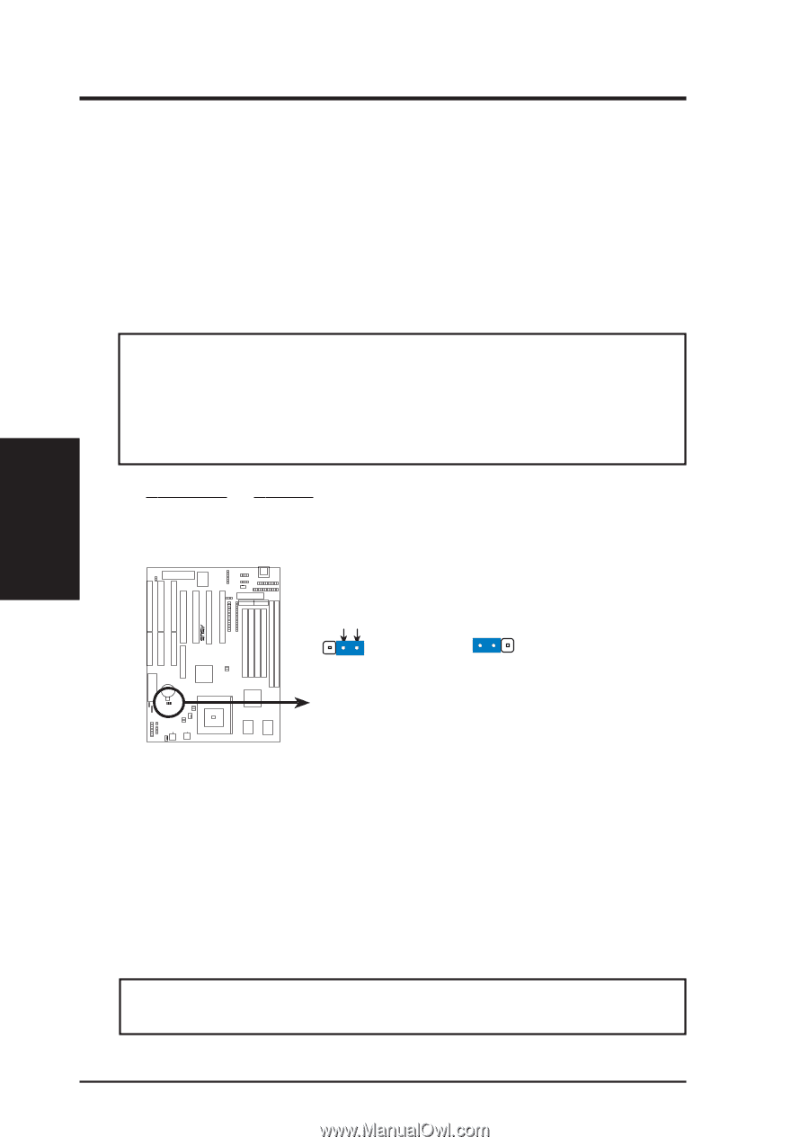
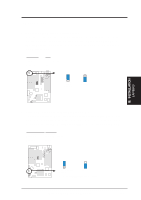
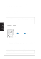
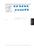
III. INSTALLATION 3. Real Time Clock (RTC) RAM (RTCLR) The CMOS RAM is powered by the onboard button cell battery. To clear the RTC data: (1) Turn off your computer, (2) Move this jumper to "Clear Data," (3) Move the jumper back to "Operation," (4) Turn on your computer, (5) Hold down during bootup and enter BIOS setup to re-enter user preferences. Battery Test Jumper (RTCLR) You can test the battery's current by removing this jumper and attaching a current meter to pins 2&3. WARNING! You must unplug the power cord to your power supply to ensure that there is no power to your motherboard. The CMOS RAM containing BIOS setup information may be cleared by this action. You should enter BIOS to "Load Setup Defaults" and re-enter any user information after removing and reapplying this jumper. RTC RAM Operation Clear Data RTCLR [2-3] (Default) [1-2] (momentarily) R III. INSTALLATION (Jumpers) Battery Test RTCLR Operation (Default) RTCLR Clear Data RTC RAM (Operation / Clear Data) 4. CPU External (BUS) Frequency Selection (FS0, FS1, FS2) These jumpers tell the clock generator what frequency to send to the CPU. These allow the selection of the CPU's External frequency (or BUS Clock). The BUS Clock times the BUS Ratio equals the CPU's Internal frequency (the advertised CPU speed). 5. CPU to BUS Frequency Ratio (BF0, BF1, BF2) These jumpers set the frequency ratio between the Internal frequency of the CPU and the External frequency (called the BUS Clock) within the CPU. These must be set together with the above jumpers CPU External (BUS) Frequency Selection. WARNING! Frequencies above 66MHz exceed the specifications for the onboard Intel Chipset and are not guaranteed to be stable. 16 ASUS TX97-E User's Manual
-
 1
1 -
2
-
3
-
4
-
5
-
6
-
7
-
8
-
9
-
10
-
 11
11 -
 12
12 -
 13
13 -
 14
14 -
 15
15 -
 16
16 -
 17
17 -
 18
18 -
 19
19 -
 20
20 -
 21
21 -
22
-
23
-
24
-
25
-
26
-
27
-
28
-
29
-
30
-
31
-
32
-
33
-
34
-
35
-
36
-
37
-
38
-
39
-
40
-
41
-
42
-
43
-
44
-
45
-
46
-
47
-
48
-
49
-
50
-
51
-
52
-
53
-
54
-
55
-
56
-
57
-
58
-
59
-
60
-
61
-
62
-
63
-
64
 |
 |