Asus Terminator C3 Terminator C3V User Manual
Asus Terminator C3 Manual
 |
View all Asus Terminator C3 manuals
Add to My Manuals
Save this manual to your list of manuals |
Asus Terminator C3 manual content summary:
- Asus Terminator C3 | Terminator C3V User Manual - Page 1
® Terminator 1 Barebone System Model C3 User Guide - Asus Terminator C3 | Terminator C3V User Manual - Page 2
COMPUTER INC. ("ASUS"). Product warranty or service will not be extended if: (1) the product is repaired, modified or altered, unless such repair, modification of alteration is authorized in writing by ASUS; or (2) the serial number of the product is defaced or missing. ASUS PROVIDES THIS MANUAL - Asus Terminator C3 | Terminator C3V User Manual - Page 3
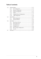
information vii About this guide viii System package contents x Chapter 1: System Introduction 1.1 Welcome 1-2 disk drive 2-13 2.9 Re-connecting cables 2-15 2.9.1 LED cables 2-15 2.9.2 UAEX module 2-16 2.10 Replacing the cover 2-17 2.11 Connecting external devices 2-19 2.12 Power supply - Asus Terminator C3 | Terminator C3V User Manual - Page 4
3.1 Installing an operating system 3-2 3.2 Support CD information 3-2 3.2.1 Running the support CD 3-2 3.2.2 Drivers menu 3-3 3.2.3 Utilities menu 3-4 3.2.4 ASUS Contact information 3-5 3.2.5 Other information 3-6 3.3 Software information 3-8 3.3.1 ASUS PC Probe 3-8 3.3.2 ASUS Update 3-12 - Asus Terminator C3 | Terminator C3V User Manual - Page 5
Memory Configuration 5-14 5.4.3 Chipset Configuration 5-15 5.4.4 PCIPnP 5-16 5.4.5 Onboard Device Configuration 5-17 5.4.6 USB Configuration 5-19 5.5 Power Menu 5-20 5.5.1 APM Configuration 5-21 5.5.2 Hardware Monitor 5-24 5.6 Boot Menu 5-26 5.6.1 Boot Device Priority 5-26 5.6.2 Removable - Asus Terminator C3 | Terminator C3V User Manual - Page 6
not installed and used in accordance with manufacturer's instructions, may cause harmful interference to radio communications. However The use of shielded cables for connection of the monitor to the graphics card is required to assure compliance with FCC regulations. Changes or modifications to this - Asus Terminator C3 | Terminator C3V User Manual - Page 7
power supply is broken, do not try to fix it by yourself. Contact a qualified service technician or your retailer. Operation safety • Before installing devices into the system . • If you encounter technical problems with the product, contact a qualified service technician or your retailer. Lithium- - Asus Terminator C3 | Terminator C3V User Manual - Page 8
About this guide Audience This guide provides general information and installation instructions about the ASUS Terminator 1 barebone system. This guide is intended for experienced users and integrators with hardware knowledge of personal computers. How this guide is organized This guide contains the - Asus Terminator C3 | Terminator C3V User Manual - Page 9
Conventions used in this guide W A R N I N G : Information to prevent injury to yourself when trying to complete a task. C A U T I O N : Information to prevent damage to the components when trying to complete a task. I M P O R T A N T : Instructions that you MUST follow to complete a task. N O T E : - Asus Terminator C3 | Terminator C3V User Manual - Page 10
package contents Check your ASUS Terminator 1 package for the following items: 1 . ASUS Terminator 1 barebone system with: • ASUS C3V motherboard with onboard VIA C3 CPU • Floppy disk drive • Optical drive (optional)* 2. Power cable and plug 3. Support CD 4. User guide * CD-ROM/CD-RW/DVD-ROM/DVD - Asus Terminator C3 | Terminator C3V User Manual - Page 11
System introduction Chapter 1 This chapter gives a general description of the ASUS Terminator 1 C3 barebone system, including introduction on the front and rear panel features, and the internal features. ASUS Terminator 1 C3 barebone system - Asus Terminator C3 | Terminator C3V User Manual - Page 12
home entertainment feature. The system comes in a stylish mini-tower casing, and is powered by the ASUS C3V motherboard that comes with a VIA C3 processor. 1.2 Front panel The ASUS Terminator 1 barebone system is composed of the ASUS C3V motherboard, a power supply, and a floppy disk drive. The CD - Asus Terminator C3 | Terminator C3V User Manual - Page 13
. H D D L E D . This LED lights up when data is being read from or written to the hard disk drive. 7 . F r o n t p a n e l I / O d o o r . Flip up a headphone with a stereo mini-plug. 1 0 . M i c r o p h o n e p o r t . This port connects a microphone. ASUS Terminator 1 C3 barebone system 1-3 - Asus Terminator C3 | Terminator C3V User Manual - Page 14
The system rear panel includes the power socket and several I/O ports that allow convenient connection of devices. 1 2 3 4 5 6 7 8 9 10 11 12 13 115V/230V Voltage selector 1 . G A M E / M I D I p o r t . This port connects a joystick or game pad for playing games, and MIDI devices for audio - Asus Terminator C3 | Terminator C3V User Manual - Page 15
voltage supply in your area. If the voltage supply in your area is 100-127 V, set the switch to 115 V. If the voltage supply in your area is 200-240 V, set the switch to 230 V. Setting the switch to 115 V in a 230 V environment will seriously damage the system! ASUS Terminator 1 C3 barebone system - Asus Terminator C3 | Terminator C3V User Manual - Page 16
out. The system may come with either a PFC (Power Factor Correction) or non-PFC power supply. 1 3 4 5 2 6 7 1. Game/MIDI/COM1 extension module 2. Motherboard 3. Two 5.25" drive bays (Optional CD-ROM) 4. 3.5" HDD drive bay 5. 3.5" floppy drive 6. PFC/Non-PFC power supply 7. USB/audio board - Asus Terminator C3 | Terminator C3V User Manual - Page 17
Basic installation Chapter 2 This chapter gives step-by-step instructions on how to install components into the barebone system. ASUS Terminator 1 C3 barebone system - Asus Terminator C3 | Terminator C3V User Manual - Page 18
card(s) 3. Hard disk drive 4. Optical drive Tool Phillips (cross) screw driver 2.2 Before you proceed Take note of the following precautions before you install components into the system. • Use a grounded wrist strap or touch a safely grounded object or a metal object, such as the power supply - Asus Terminator C3 | Terminator C3V User Manual - Page 19
, then push the inner chassis with your thumbs while pulling the panel with your other fingers. 3. While supporting the front panel with one hand, place your other hand on the top rear edge of the cover and carefully lift the cover from the chassis. Screw ASUS Terminator 1 C3 barebone system 2-3 - Asus Terminator C3 | Terminator C3V User Manual - Page 20
and voltage selector switch are attached to a metal module secured to the Power socket rear panel by a screw. Remove module screw the screw to release the power socket module. Power socket module You must release the power socket module from the rear panel before detaching the drive frame to avoid - Asus Terminator C3 | Terminator C3V User Manual - Page 21
3. Place your thumb on the right edge of the power socket module, then slide the module to the right until it is completely detached from the rear from the chassis when installing components. 5. Carefully lay the drive frame alongside the main chassis frame. ASUS Terminator 1 C3 barebone system 2-5 - Asus Terminator C3 | Terminator C3V User Manual - Page 22
comes with two Double Data Rate (DDR) Dual Inline Memory Module (DIMM) sockets. These sockets support up to 2 GB system memory using unbuffered ECC or non-ECC PC2100 DIMMs. ® C3V 104 Pins 80 Pins C3V 184-pin DDR DIMM sockets 2.5.1 Memory configurations You may install any DDR DIMMs with 64 MB - Asus Terminator C3 | Terminator C3V User Manual - Page 23
. A DDR DIMM is keyed with a notch so that it fits in only one direction. DO NOT force a DIMM into a socket to avoid damaging the DIMM. ASUS Terminator 1 C3 barebone system 2-7 - Asus Terminator C3 | Terminator C3V User Manual - Page 24
slot PCI slot The PCI slot supports PCI cards such as a LAN card, SCSI card, USB card, and other cards that comply with PCI specifications. The figure shows a LAN card installed on a PCI slot. Make sure to unplug the power cord before adding or removing expansion cards. Failure to do so may cause - Asus Terminator C3 | Terminator C3V User Manual - Page 25
card After installing the expansion card, configure it by adjusting the software settings. 1. Turn on the system and change the necessary BIOS settings, if any. See Chapter 5 for information on BIOS setup. 2. Install the software drivers for the expansion card. ASUS Terminator 1 C3 barebone system - Asus Terminator C3 | Terminator C3V User Manual - Page 26
Communications Port (COM1) Onboard Audio Standard Floppy Disk Controller Printer Port (LPT1) System CMOS/Real Time Clock ACPI Mode PCI slot USB 1.1 UHCI 1 USB 1.1 UHCI 1 USB 1.1 UHCI 1 USB 2.0 EHCI Onboard Audio Onboard LAN ABCDE F G H used shared used shared used shared - - - - - shared - Asus Terminator C3 | Terminator C3V User Manual - Page 27
Installing an optical drive An optical drive is an optional item in this barebone system. Refer to the instructions in this section if you acquired a model without an optical drive. Follow the lower 5.25-inch drive bay. 5.25-inch drive bay CD-ROM screws ASUS Terminator 1 C3 barebone system 2-11 - Asus Terminator C3 | Terminator C3V User Manual - Page 28
5. Connect a power cable from the power supply to the power connector at the back of the optical drive. one end of the Optical drive audio cable CD-ROM audio cable to the IDE ribbon cable 4-pin connector at the back of the CD-ROM. Red stripe to Pin 1 Power cable 8. Connect the other end of - Asus Terminator C3 | Terminator C3V User Manual - Page 29
The chassis has one 3.5-inch hard disk drive (HDD) bay right under the 5.25-inch bay. The following figures show the internal and external views holes align with the holes on the bay marked HDD. 4. Drive screws into the HDD screw holes. ASUS Terminator 1 C3 barebone system HDD screw holes 2-13 - Asus Terminator C3 | Terminator C3V User Manual - Page 30
5. Connect a power cable from the power supply to the power connector at the back of the HDD. Use the cable with the white connector. 6. Connect one end of the IDE hard disk ribbon cable to the IDE interface at the back of the HDD, matching the red stripe on the cable with Pin 1 on the IDE - Asus Terminator C3 | Terminator C3V User Manual - Page 31
PANEL RESET IDELED PWRBTN SMI * Requires an ATX power supply. • Connect the power switch and power LED cables to their respective leads in the PANEL connector on the motherboard. • Connect the H D D L E D cable to the 2-pin lead marked IDELED. ASUS Terminator 1 C3 barebone system 2-15 - Asus Terminator C3 | Terminator C3V User Manual - Page 32
2.9.2 UAEX module The system front I/O panel has a UAEX module that contains the front panel I/O ports and the connectors to the motherboard. USB T: Port0 B: Port1 UAEX ® LOUT LO2 MIC MIC2 - Asus Terminator C3 | Terminator C3V User Manual - Page 33
should snap perfectly to the chassis edge. 3. Re-attach the power socket module and secure it with the screw you removed earlier. Side tab 4. Turn the chassis upright. 5. Place the cover over the chassis leaving about two inches from the rear panel. ASUS Terminator 1 C3 barebone system 2-17 - Asus Terminator C3 | Terminator C3V User Manual - Page 34
5. Fit the rail tabs on the sides and bottom of the cover to the edges of the chassis. Rail tabs 6. Push the cover towards the rear until it fits. The locking tab snaps into the hole on the chassis, indicating that the cover is in place. Locking tab Locking tab hole Firmly push the cover to - Asus Terminator C3 | Terminator C3V User Manual - Page 35
2.11 Connecting external devices The figure below shows the specific connectors and devices that you can connect to the rear panel ports. Serial PS/2 KB VGA Line Out Line In Mic RJ-45 Game/ MIDI PS/2 Mouse Parallel AC USB ASUS Terminator 1 C3 barebone system 2-19 - Asus Terminator C3 | Terminator C3V User Manual - Page 36
Protection (OVP) Output Voltage Maximum Voltage +5V 6.5V +12V 15.6V +3.3V 4.3V The power supply will shut down and latch off for shorting +5V, +12V, -12V, or +3.3V. By shorting +5VSB, the power supply can latch down or automatically recover when the fault condition is removed. 2-20 Chapter - Asus Terminator C3 | Terminator C3V User Manual - Page 37
Starting up Chapter 3 This chapter helps you power up your system and install drivers and utilities that came with the support CD. ASUS Terminator 1 C3 barebone system - Asus Terminator C3 | Terminator C3V User Manual - Page 38
. Visit the ASUS website for updates. 3.2.1 Running the support CD To begin using the support CD, simply insert the CD into your CD-ROM drive. If Autorun is enabled in your computer, the Drivers menu automatically appears on your screen. 3-2 Click an item to install Click an icon to display more - Asus Terminator C3 | Terminator C3V User Manual - Page 39
the ADI® 1980/1888 SoundMAX® audio driver and application. VIA 10/100Mb LAN Driver Installs the VIA 10/100Mb LAN driver. VIA VT6420 (VT8237) SATA driver Installs the VIA VT6420 (VT8237) Serial ATA driver. USB 2.0 Driver Installs the USB 2.0 driver. ASUS Terminator 1 C3 barebone system 3-3 - Asus Terminator C3 | Terminator C3V User Manual - Page 40
, CPU temperature, and system voltages, and alerts you of any detected problems. This utility helps you keep your computer at a healthy operating condition. ASUS Update Installs the ASUS Update. This program allows you to download the latest version of the BIOS from the ASUS website. Before using - Asus Terminator C3 | Terminator C3V User Manual - Page 41
the Microsoft® Direct X driver. PC-CILLIN 2002 Installs the PC-cillin 2002 anti-virus software. View the PC-cillin online help for detailed information. 3.2.4 ASUS Contact information Click the C o n t a c t tab to display the ASUS contact information. ASUS Terminator 1 C3 barebone system 3-5 - Asus Terminator C3 | Terminator C3V User Manual - Page 42
on the top right of the screen give additional information on the motherboard and the contents of the support CD. Click an icon to display the specified information. Motherboard Info Displays the general specifications of the motherboard. The screen image below is for general reference only. The - Asus Terminator C3 | Terminator C3V User Manual - Page 43
in graphical format. Technical support form Displays the ASUS Technical Support Request Form that you have to fill out when requesting technical support. Filelist Displays the contents of the support CD and a brief description of each in text format. ASUS Terminator 1 C3 barebone system 3-7 - Asus Terminator C3 | Terminator C3V User Manual - Page 44
in the support CD have wizards that will conveniently guide you through the installation. View the online help or readme file that came with the software for more information. 3.3.1 ASUS PC Probe ASUS PC Probe is a convenient utility to continuously monitor your computer system's vital components - Asus Terminator C3 | Terminator C3V User Manual - Page 45
Using ASUS PC Probe Monitoring Monitor Summary Shows a summary of the items being monitored. Temperature Monitor Shows the PC temperature. increase the threshold level or down to decrease the threshold level) Voltage Monitor Shows the PC voltages. ASUS Terminator 1 C3 barebone system 3-9 - Asus Terminator C3 | Terminator C3V User Manual - Page 46
and voltages. CPU Cooling System Setup Lets you select when to enable software CPU cooling. If you select When CPU Over-heated, the CPU cooling system is enabled whenever the CPU free space of the PC's hard disk drives and the file allocation table or file system used. 3-10 Chapter 3: Starting up - Asus Terminator C3 | Terminator C3V User Manual - Page 47
to the PC, such as CPU type, CPU speed, and internal/external frequencies, and memory size. Utility Lets you run programs outside of the ASUS Probe modules. To run a program, click E x e c u t e P r o g r a m. This feature is currently unavailable. ASUS Terminator 1 C3 barebone system 3-11 - Asus Terminator C3 | Terminator C3V User Manual - Page 48
all system monitoring. When the ASUS PC Probe senses a problem with your PC, portions of the ASUS PC Probe icon change to red, the PC speaker beeps, and the ASUS PC Probe monitor appears. 3.3.2 ASUS Update The ASUS Update is a utility that allows you to update the motherboard BIOS and drivers. This - Asus Terminator C3 | Terminator C3V User Manual - Page 49
screens to complete the update process. If you selected the option to update the BIOS from a file, a window pops up prompting you to locate the file. Select the file, click S a v e, then follow the screen instructions to complete the update process. ASUS Terminator 1 C3 barebone system 3-13 - Asus Terminator C3 | Terminator C3V User Manual - Page 50
3-14 Chapter 3: Starting up - Asus Terminator C3 | Terminator C3V User Manual - Page 51
Motherboard info Chapter 4 This chapter gives information about the motherboard that came with the system. This chapter includes the motherboard layout, jumper settings, and connector locations. ASUS Terminator T1 C3 barebone system - Asus Terminator C3 | Terminator C3V User Manual - Page 52
4.1 Introduction The ASUS C3V motherboard comes already installed in the ASUS Terminator 1 C3 barebone system. This chapter provides technical information about the motherboard for future upgrades or system reconfiguraiton. 4.2 Motherboard layout ATXPWR PS/2 T:Mouse B:Keyboard VGA IOC_MB1 - Asus Terminator C3 | Terminator C3V User Manual - Page 53
or in sleep mode. • Make sure to set the jumpers to +5VSB if you want to wake up the system from S3, S4, and S5 sleep mode. ® C3V C3V USB device wake-up USBPWR12 2 1 +5V 3 2 +5VSB (Default) USBPWR34 USBPWR56 USBPWR78 12 23 +5V +5VSB (Default) ASUS Terminator T1 C3 barebone system 4-3 - Asus Terminator C3 | Terminator C3V User Manual - Page 54
powers the RAM data in CMOS, which include system setup information such as system passwords. To erase the RTC RAM: 1. Turn OFF the computer and unplug the power power cord and turn ON the computer. 6. Hold down the key during the boot process and enter BIOS setup to re-enter data. ® C3V C3V - Asus Terminator C3 | Terminator C3V User Manual - Page 55
slave device by setting its jumper accordingly. Refer to the hard disk documentation for the jumper settings. • Pin 20 on the IDE C3V C3V IDE connectors PRI_IDE SEC_IDE NOTE: Orient the red markings (usually zigzag) on the IDE ribbon cable to PIN 1. PIN 1 ASUS Terminator T1 C3 barebone system - Asus Terminator C3 | Terminator C3V User Manual - Page 56
disk drive connector 3 . Internal audio connectors (4-pin CD, AUX) These connectors allow you to receive stereo audio input from sound sources such as an optical drive, TV tuner, or MPEG card. ® C3V CD AUX C3V Internal audio connectors Right Audio Channel Ground Left Audio Channel Right Audio - Asus Terminator C3 | Terminator C3V User Manual - Page 57
(5-1 pin MIC_LOUT) This connector is for a chassis-mounted front panel audio I/O module that supports legacy AC'97 audio standard. ® C3V MIC_LOUT MIC Signal MIC PWR 1 GND Head set Right channel Head set Left channel C3V Front panel audio connector ASUS Terminator T1 C3 barebone system 4-7 - Asus Terminator C3 | Terminator C3V User Manual - Page 58
. Insufficient air flow inside the system may damage the motherboard components. These are not jumpers! Do not place jumper caps on the fan connectors! 7 . IO extension module connector (22-pin IOC_MB) This connector is for the CGAEX extension module. ® C3V C3V IOC_MB connector COM1 GAME - Asus Terminator C3 | Terminator C3V User Manual - Page 59
(S/PDIF) port(s). Connect the S/PDIF module cable to this connector, then install the module to a slot opening at the back of the system chassis. The S/PDIF module is purchased separately. ® C3V +5V SPDIFOUT GND C3V Digital audio connector SPDIF_OUT ASUS Terminator T1 C3 barebone system 4-9 - Asus Terminator C3 | Terminator C3V User Manual - Page 60
of these connectors, then install the module to a slot opening at the back of the system chassis. These USB connectors comply with USB 2.0 specification that supports up to 480 Mbps connection speed. ® C3V C3V USB 2.0 connectors 11. TV-out/S-Video out connector (10-1 pin J1) This connector is for - Asus Terminator C3 | Terminator C3V User Manual - Page 61
supports several chassis-mounted functions. ® C3V PLED SPEAKER +5 V PLED +5V Ground Ground Speaker IDE_LED+ IDE_LED- ExtSMI# Ground PWRBIN Ground Reset Ground C3V System panel connectors RESET IDELED PWRBTN SMI * Requires an ATX power supply. ASUS Terminator T1 C3 barebone system - Asus Terminator C3 | Terminator C3V User Manual - Page 62
3-pin PLED) This 3-pin connector is for the system power LED. Connect the chassis power LED cable to this connector. The system power LED lights up when you turn on the system power, and blinks when the system is in sleep mode. • Hard disk drive activity LED (Red 2-pin IDELED) This 2-pin connector - Asus Terminator C3 | Terminator C3V User Manual - Page 63
BIOS information Chapter 5 This chapter tells how to change system settings through the BIOS Setup menus. This chapter includes detailed descriptions of the BIOS parameters. ASUS Terminator 1 C3 barebone system - Asus Terminator C3 | Terminator C3V User Manual - Page 64
System (BIOS) setup. 1. A w a r d B I O S F l a s h U t i l i t y (Updates the BIOS using a floppy disk during POST.) 2. A S U S C r a s h F r e e B I O S (Updates the BIOS using a bootable floppy disk when the BIOS gets corrupted.) 3. A S U S U p d a t e (Updates the BIOS in Windows® environment - Asus Terminator C3 | Terminator C3V User Manual - Page 65
1. Download the latest BIOS file from the ASUS website (www.asus.com). Rename the file to C3V.BIN and save it to the bootable floppy disk you created earlier. 2. Insert the disk that contains the new BIOS file into the floppy drive. 3. Reboot the computer. ASUS Terminator 1 C3 barebone system 5-3 - Asus Terminator C3 | Terminator C3V User Manual - Page 66
during POST to display the following screen. 5. AWDFLASH checks the new BIOS file from the floppy disk. 6. After verification, AWDFLASH flashes the new BIOS file. Do not shut down the computer during the flash process. 7. After the new BIOS file is copied, the computer returns to POST. 5-4 Chapter - Asus Terminator C3 | Terminator C3V User Manual - Page 67
Checking for floppy... Floppy found! Reading file "c3v.bin". Completed. Start flashing... DO NOT shut down or reset the system while updating the BIOS! Doing so may cause system boot failure! 4. When the BIOS update process is complete, reboot the system. ASUS Terminator 1 C3 barebone system 5-5 - Asus Terminator C3 | Terminator C3V User Manual - Page 68
to update the motherboard BIOS in Windows® environment. This utility is available in the support CD that comes with the motherboard package. ASUS Update requires an Internet connection either through a network or an Internet Service Provider (ISP). Go to section "3.3.2 ASUS Update" for details on - Asus Terminator C3 | Terminator C3V User Manual - Page 69
and make your selections among the predetermined choices. Because the BIOS software is constantly being updated, the following BIOS setup screens and descriptions are for reference purposes only, and may not exactly match what you see on your screen. ASUS Terminator 1 C3 barebone system 5-7 - Asus Terminator C3 | Terminator C3V User Manual - Page 70
system configuration. ADVANCED Use this menu to enable and make changes to the advanced features. POWER Use this menu to configure and enable Power Management features. BOOT Use this menu to configure the default system Displays the General Help screen from anywhere in the BIOS Setup - Asus Terminator C3 | Terminator C3V User Manual - Page 71
window, the BIOS setup Setup default values. While moving around through the Setup program, note that explanations appear in the Item Specific Help window located to the right of each menu. This window displays the help text for the currently highlighted field. ASUS Terminator 1 C3 barebone system - Asus Terminator C3 | Terminator C3V User Manual - Page 72
When you enter the Setup program, the following screen appears. System Time System Date 11:19:20 Mon., Jul 26 2004 Legacy Diskette A [1.44M, 3.5 in.] Primary IDE Master Primary IDE Slave Secondary IDe Master Secondary IDE Slave HDD SMART Monitoring [IBM-DJNA-371350] [None] [ASUS DVD-ROM] [None - Asus Terminator C3 | Terminator C3V User Manual - Page 73
disk drive is too old or too new. If the hard disk was already formatted on an older system, Setup may detect incorrect parameters. In these cases, select [Manual] to manually enter the IDE hard disk : [Auto] [Mode 0] [Mode 1] [Mode 2] [Mode 3] [Mode 4] ASUS Terminator 1 C3 barebone system 5-11 - Asus Terminator C3 | Terminator C3V User Manual - Page 74
field automatically displays the amount of conventional memory detected by the system during the boot process. 5.4 Advanced Menu The Advanced menu items allow you to change the settings for the CPU and other system values may cause the system to malfunction. CPU Configuration - Asus Terminator C3 | Terminator C3V User Manual - Page 75
5.4.1 CPU Configuration The items in this menu show the CPU-related information auto-detected by the BIOS. CPU Configuration CPU Type CPU Speed Cache RAM Current FSB Frequency VIA C3 800A MHz 64 K 133 MHz Select Menu Item Specific Help ASUS Terminator 1 C3 barebone system 5-13 - Asus Terminator C3 | Terminator C3V User Manual - Page 76
memory configuration settings. Select an item then press to display a pop-up menu with the configuration options. Memory Configuration Current . Select [Manual] to set the DRAM Timing manually. Select [Safe] to set the DRAM timing to safe value. Configuration options: [Manual] [By SPD - Asus Terminator C3 | Terminator C3V User Manual - Page 77
[CVBS] Allows you to select the primary TV connector. Configuration options: [CVBS] [S-Video 0] Init Display First [PCI Slot] Allows you to set which graphics controller to use as the primary boot device. Configuration options: [PCI slot] [AGP] ASUS Terminator 1 C3 barebone system 5-15 - Asus Terminator C3 | Terminator C3V User Manual - Page 78
press to display a pop-up menu and Play capable operating system. Select [No] if you need the BIOS to configure non- cards, like graphics accelerators or MPEG video cards, may not show colors properly. Setting this field to [Enabled] corrects this problem. If you are using standard VGA cards - Asus Terminator C3 | Terminator C3V User Manual - Page 79
to display a pop-up menu with the configuration options. Onboard Device Configuration Onboard LAN Boot ROM OnChip SATA SATA Mode AC97 Audio Onboard LAN Serial [Disabled] if you installed a PCI LAN card. Configuration options: [Auto] [Disabled] ASUS Terminator 1 C3 barebone system 5-17 - Asus Terminator C3 | Terminator C3V User Manual - Page 80
port. Configuration options: [Disabled] [201] [209] Midi Port Address [Disabled] Sets the I/O address for the MIDI I/O port. Configuration options: [Disabled] [330] [300] [290] 5-18 Chapter 5: BIOS information - Asus Terminator C3 | Terminator C3V User Manual - Page 81
the BIOS to turn on automatically when you install high speed USB devices. Configuration options: [Enabled] Disabled] USB Legacy Support [Enabled] Allows you to enable or disable support for legacy USB devices. Configuration options: [Disabled] [Enabled] ASUS Terminator 1 C3 barebone system 5-19 - Asus Terminator C3 | Terminator C3V User Manual - Page 82
power consumption. This feature turns off the video display and shuts down the hard disk after a period of inactivity. ACPI Suspend Type APM Configuration Hardware Monitor [S1 (POS)] Select Menu Item Specific Help ACPI Suspend Type [S1 (POS)] Allows you to select the ACPI state used for system - Asus Terminator C3 | Terminator C3V User Manual - Page 83
] Power Up On PCI Devices [Disabled] When set to [Enabled], this parameter allows you to turn on the system through a PCI modem. This feature requires an ATX power supply that provides at least 1A on the +5VSB lead. Configuration options: [Disabled] [Enabled] ASUS Terminator 1 C3 barebone system - Asus Terminator C3 | Terminator C3V User Manual - Page 84
then back on while the computer is off causes an initialization string that turns the system power on. Power On By RTC Alarm [ : 0] To set the time of alarm: 1. Highlight this item and press to display a pop-up menu for the hour field. 2. Key-in a value (Min=0, Max=23), 5: BIOS information - Asus Terminator C3 | Terminator C3V User Manual - Page 85
set to [Instant-Off], the system goes to soft-off when you press the power button for l e s s than 4 seconds. When set to [Suspend], press the power button for m o r e than 4 seconds to power off the system. Configuration options: [Suspend] [Instant-Off] ASUS Terminator 1 C3 barebone system 5-23 - Asus Terminator C3 | Terminator C3V User Manual - Page 86
System will shut down when CPU temperature is too high. Power Temperature [xxxoC/xxxoF ] CPU Temperature [xxxoC/xxxoF ] The onboard hardware monitor automatically detects and displays the power supply Monitor found an error. Enter Power setup menu for details." You will then be prompted to "Press - Asus Terminator C3 | Terminator C3V User Manual - Page 87
Function [Disabled] Allows you to enable or disable the ASUS Q-Fan feature that smartly adjusts the CPU fan speed for more efficient system operation. Configuration options: [Disabled] [Enabled] The following . Configuration options: [0.1 sec] ~ [1.6 sec] ASUS Terminator 1 C3 barebone system 5-25 - Asus Terminator C3 | Terminator C3V User Manual - Page 88
The Boot menu items allow you to change the system boot settings. Select an item then press to display a pop-up menu with the configuration options. Device 2nd Boot Device 3rd Boot Device 4th Boot Device [Hard Disk] [CDROM] [Disabled] [Disabled] Select Menu Item Specific Help Select - Asus Terminator C3 | Terminator C3V User Manual - Page 89
Hard Disk Drives Hard Disk Drives 1. 1st Master: IBM-DJNA-371350 2. Bootable Add-in Cards Select Menu Item Specific Help Use or arrow to select a device, then press to move it up, or to move it down the list. Press to exit this menu. ASUS Terminator 1 C3 barebone system - Asus Terminator C3 | Terminator C3V User Manual - Page 90
tests while booting. This will decrease the time needed to boot the system. Quick Boot [Enabled] Setting to [Enabled] allows the system to skip certain tests while booting, decreasing the time needed to boot the system. Configuration options: [Disabled] [Enabled] 5-28 Chapter 5: BIOS information - Asus Terminator C3 | Terminator C3V User Manual - Page 91
options: [Non-OS2] [OS2] Halt On [All Errors] Sets the system to halt on errors according to the system functions specified in each option. Configuration options: [All Errors] [No Errors] [All, But Keyboard] [All , But Diskette] [All, But Disk/Key] ASUS Terminator 1 C3 barebone system 5-29 - Asus Terminator C3 | Terminator C3V User Manual - Page 92
DISABLED!!! Press any key to continue..." 2. Press any key to return to the menu. A note about passwords The Supervisor password is required to enter the BIOS Setup program preventing unauthorized access. The User password is required to boot the system preventing unauthorized use. 5-30 Chapter - Asus Terminator C3 | Terminator C3V User Manual - Page 93
save your changes to CMOS before exiting the Setup utility. When a confirmation window appears (with a blinking [Y]): • press to save and exit • type [N], then press , or simply press , to cancel the command and return to the Exit menu ASUS Terminator 1 C3 barebone system 5-31 - Asus Terminator C3 | Terminator C3V User Manual - Page 94
other than system date, system time, and password, the BIOS asks for a confirmation before exiting. Load Setup Defaults This option allows you to load the default values for each of the parameters on the Setup menus. When you select this option or if you press , a confirmation window appears
-
 1
1 -
 2
2 -
 3
3 -
 4
4 -
 5
5 -
 6
6 -
 7
7 -
8
-
9
-
10
-
11
-
12
-
13
-
14
-
15
-
16
-
17
-
18
-
19
-
20
-
21
-
22
-
23
-
24
-
25
-
26
-
27
-
28
-
29
-
30
-
31
-
32
-
33
-
34
-
35
-
36
-
37
-
38
-
39
-
40
-
41
-
42
-
43
-
44
-
45
-
46
-
47
-
48
-
49
-
50
-
51
-
52
-
53
-
54
-
55
-
56
-
57
-
58
-
59
-
60
-
61
-
62
-
63
-
64
-
65
-
66
-
67
-
68
-
69
-
70
-
71
-
72
-
73
-
74
-
75
-
76
-
77
-
78
-
79
-
80
-
81
-
82
-
83
-
84
-
85
-
86
-
87
-
88
-
89
-
90
-
91
-
92
-
93
-
94
 |
 |
®
User Guide
Barebone System
Model C3
Terminator 1