Asus Terminator P4 533 Terminator P4-533 English user''''s manual - Page 25
ASUS Terminator P4 533 Barebone System
 |
View all Asus Terminator P4 533 manuals
Add to My Manuals
Save this manual to your list of manuals |
Page 25 highlights
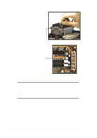
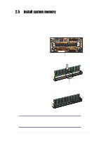
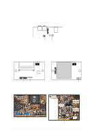
5. Connect a power cable from the power supply to the power connector at the back of the HDD. Use the cable with the white connector labeled P3. 6. Connect one end of the IDE hard disk ribbon cable to the IDE interface at the back of the HDD, matching the red stripe on the cable with Pin 1 on the IDE interface. Red Stripe to Pin 1 IDE Ribbon Cable Power Cable (P3) 7. Connect the other end of the IDE ribbon cable to the primary IDE connector (blue connector labeled IDE1) on the motherboard. Primary IDE connector (IDE1) ASUS Terminator P4 533 Barebone System 25
-
 1
1 -
2
-
3
-
4
-
5
-
6
-
7
-
8
-
9
-
10
-
11
-
12
-
13
-
14
-
15
-
16
-
17
-
18
-
19
-
 20
20 -
 21
21 -
 22
22 -
 23
23 -
 24
24 -
 25
25 -
 26
26 -
 27
27 -
 28
28 -
 29
29 -
 30
30 -
31
-
32
-
33
-
34
-
35
-
36
-
37
-
38
-
39
-
40
-
41
-
42
-
43
-
44
-
45
-
46
-
47
-
48
-
49
-
50
-
51
-
52
-
53
-
54
-
55
-
56
-
57
-
58
-
59
-
60
-
61
-
62
-
63
-
64
-
65
-
66
-
67
-
68
-
69
-
70
-
71
-
72
-
73
-
74
-
75
-
76
-
77
-
78
-
79
-
80
-
81
-
82
-
83
-
84
-
85
-
86
-
87
-
88
-
89
-
90
-
91
-
92
-
93
-
94
-
95
-
96
-
97
-
98
 |
 |

ASUS Terminator P4 533 Barebone System
25
5.
Connect a power cable from
the power supply
to the power
connector at the back of the
HDD. Use the cable with the
white connector labeled P3.
6.
Connect one end of the IDE
hard disk ribbon cable to the
IDE interface at the back of
the HDD, matching the red
stripe on the cable with Pin 1
on the IDE interface.
Red Stripe to Pin 1
IDE Ribbon Cable
Power Cable (P3)
7.
Connect the other end of the
IDE ribbon cable to the
primary IDE connector (blue
connector labeled IDE1) on
the motherboard.
Primary IDE connector
(IDE1)