Asus Terminator P4 Terminator P4-533 English user''''s manual - Page 29
Re-connect cables
 |
View all Asus Terminator P4 manuals
Add to My Manuals
Save this manual to your list of manuals |
Page 29 highlights
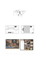
2.9 Re-connect cables You may have disconnected some cables when you were installing components. You must re-connect these cables before you replace the chassis cover. 2.9.1 LED cables Power Switch Power LED HDD LED PANEL1 Connector Power LED Speaker Connector +5VSB PLED +5V Ground Ground Speaker +5 V MLED ExtSMI# Ground PWR Ground Reset Ground PANEL1 IDE_LED1 Message LED SMI Lead Reset SW ATX Power Switch* * Requires an ATX power supply. • Connect the power switch and power LED cables to their respective leads in the PANEL1 connector on the motherboard. • Connect the HDD LED cable to the 2-pin lead marked IDE_LED1. ASUS Terminator P4 533 Barebone System 29
-
 1
1 -
2
-
3
-
4
-
5
-
6
-
7
-
8
-
9
-
10
-
11
-
12
-
13
-
14
-
15
-
16
-
17
-
18
-
19
-
20
-
21
-
22
-
23
-
 24
24 -
 25
25 -
 26
26 -
 27
27 -
 28
28 -
 29
29 -
 30
30 -
 31
31 -
 32
32 -
 33
33 -
 34
34 -
35
-
36
-
37
-
38
-
39
-
40
-
41
-
42
-
43
-
44
-
45
-
46
-
47
-
48
-
49
-
50
-
51
-
52
-
53
-
54
-
55
-
56
-
57
-
58
-
59
-
60
-
61
-
62
-
63
-
64
-
65
-
66
-
67
-
68
-
69
-
70
-
71
-
72
-
73
-
74
-
75
-
76
-
77
-
78
-
79
-
80
-
81
-
82
-
83
-
84
-
85
-
86
-
87
-
88
-
89
-
90
-
91
-
92
-
93
-
94
-
95
-
96
-
97
-
98
 |
 |

ASUS Terminator P4 533 Barebone System
29
2.9
Re-connect cables
You may have disconnected some cables when you were installing
components. You must re-connect these cables before you replace the
chassis cover.
2.9.1
LED cables
•
Connect the
power switch
and
power LED
cables to their respective
leads in the PANEL1 connector on the motherboard.
•
Connect the
HDD LED
cable to the 2-pin lead marked IDE_LED1.
Power Switch
Power LED
HDD LED
PANEL1
IDE_LED1
*
Requires an ATX power supply.
PLED
Ground
MLED
PWR
+5VSB
+5V
Speaker
Speaker
Connector
Power LED
Ground
+5 V
Reset SW
SMI Lead
Message LED
ExtSMI#
Ground
Reset
Ground
Ground
ATX Power
Switch*
PANEL1 Connector