Asus V2-PH1 Vintage2-PH1 User''s Manual for English Edition
Asus V2-PH1 Manual
 |
View all Asus V2-PH1 manuals
Add to My Manuals
Save this manual to your list of manuals |
Asus V2-PH1 manual content summary:
- Asus V2-PH1 | Vintage2-PH1 User''s Manual for English Edition - Page 1
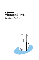
Vintage2-PH1 Barebone System - Asus V2-PH1 | Vintage2-PH1 User''s Manual for English Edition - Page 2
"). Product warranty or service will not be extended if: (1) the product is repaired, modified or altered, unless such repair, modification of alteration is authorized in writing by ASUS; or (2) the serial number of the product is defaced or missing. ASUS PROVIDES THIS MANUAL "AS IS" WITHOUT WARRANTY - Asus V2-PH1 | Vintage2-PH1 User''s Manual for English Edition - Page 3
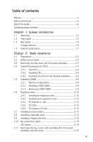
Table of contents Notices vi Safety information vii About this guide viii System package contents x Chapter 1: System Introduction 1.1 Installing a hard disk drive 2-15 2.9 Installing a floppy disk drive 2-18 2.10 Re-connecting cables 2-19 LED cables 2-19 2.11 Removing the bay covers and - Asus V2-PH1 | Vintage2-PH1 User''s Manual for English Edition - Page 4
system 3-2 3.2 Powering up 3-2 3.3 Support CD information 3-2 3.3.1 Running the support CD 3-3 3.3.2 Utilities menu 3-4 3.2.3 Manuals menu 3-5 3.3.4 ASUS Contact information 3-6 3.4 Software information 3-7 3.4.1 ASUS Update 3-7 3.4.2 ASUS PC Probe II 3-9 Chapter 4: Motherboard Info - Asus V2-PH1 | Vintage2-PH1 User''s Manual for English Edition - Page 5
Configuration 5-23 5.4.4 Chipset 5-25 5.4.5 Onboard Devices Configuration 5-26 5.4.6 PCI PnP 5-28 5.5 Power menu 5-29 5.5.1 Suspend Mode 5-29 5.5.2 ACPI 2.0 Support 5-29 5.5.3 ACPI APIC Support 5-29 5.5.4 APM Configuration 5-30 5.5.5 Hardware Monitor 5-32 5.6 Boot menu 5-34 5.6.1 Boot Device - Asus V2-PH1 | Vintage2-PH1 User''s Manual for English Edition - Page 6
. This equipment generates, uses and can radiate radio frequency energy and, if not installed and used in accordance with manufacturerʼs instructions, may cause harmful interference to radio communications. However, there is no guarantee that interference will not occur in a particular installation - Asus V2-PH1 | Vintage2-PH1 User''s Manual for English Edition - Page 7
connected. • If the power supply is broken, do not try to fix it by yourself. Contact a qualified service technician or your retailer. a stable surface. • If you encounter technical problems with the product, contact a qualified service technician or your retailer. Lithium-Ion Battery Warning - Asus V2-PH1 | Vintage2-PH1 User''s Manual for English Edition - Page 8
This chapter provides step-by-step instructions on how to install components in the system. 3. Chapter 3: Starting up This chapter helps you power up the system and install drivers and utilities from the support CD. 4. Chapter 4: Motherboard information This chapter gives information about - Asus V2-PH1 | Vintage2-PH1 User''s Manual for English Edition - Page 9
Conventions used in this guide WARNING: Information to prevent injury to yourself when trying to complete a task. CAUTION: Information to prevent damage to the components when trying to complete a task. IMPORTANT: Instructions that you MUST follow to complete a task. NOTE: Tips and additional - Asus V2-PH1 | Vintage2-PH1 User''s Manual for English Edition - Page 10
-PH1 system package for the following items. If any of the items is damaged or missing, contact your retailer immediately. Item description 1. ASUS Vintage2-PH1 barebone system with • ASUS motherboard • 300 W PFC power supply unit • ASUS chassis 2. Cable • AC power cable 3. Support CD 4. User guide - Asus V2-PH1 | Vintage2-PH1 User''s Manual for English Edition - Page 11
System introduction Chapter 1 This chapter gives a general description of the ASUS Vintage2-PH1. The chapter lists the system features including introduction on the front and rear panel, and internal components. ASUS Vintage2-PH1 - Asus V2-PH1 | Vintage2-PH1 User''s Manual for English Edition - Page 12
1.1 Welcome! Thank you for choosing the ASUS Vintage2-PH1! The ASUS Vintage2-PH1 is an all-in-one barebone system with a versatile home entertainment feature. The system comes in a stylish mini-tower casing and powered by the ASUS motherboard that supports the Intel® Pentium® D, Intel® Pentium® 4 or - Asus V2-PH1 | Vintage2-PH1 User''s Manual for English Edition - Page 13
high-speed connectivity for audio/video devices, storage peripherals, PCs, or protable devices. 4. Power button. Press this button to turn the system on. 5. Reset button. Press this button a stereo mini-plug. 9. Microphone port. This Mic (pink) port connects a microphone. ASUS Vintage2-PH1 1-3 - Asus V2-PH1 | Vintage2-PH1 User''s Manual for English Edition - Page 14
K SIDE S P K C T R BASS LINE IN FRONT MIC IN 10 18 11 12 19 13 1. Power connector. This connector is for the power cable and plug. 2. Voltage selector. This switch allows you to adjust the system input voltage according to the voltage supply in your area. See the "Voltage selector" section on - Asus V2-PH1 | Vintage2-PH1 User''s Manual for English Edition - Page 15
port connects the side speakers in an 8-channel audio configuration. 10. Rear Speaker Out port (orange). This port connects the rear audio sources. 14. Power supply unit fan vent. This vent is for the PSU fan that provides ventilation inside the power supply unit. 15. Chassis ASUS Vintage2-PH1 1-5 - Asus V2-PH1 | Vintage2-PH1 User''s Manual for English Edition - Page 16
Voltage selector The PSU has a 115 V/230 V voltage selector switch located beside the power connector. Use this switch to select the appropriate system input voltage according to the voltage supply in your area. If the voltage supply in your area is 100-127 V, set this switch to 115 V. If the - Asus V2-PH1 | Vintage2-PH1 User''s Manual for English Edition - Page 17
Super I/O F_PANEL 3 1 4 1. Front panel cover 2. 5.25-inch optical drive bays 3. Hard disk drive bay 4. Floppy disk drive bay 5. Power supply unit 6. CPU socket 7. DIMM sockets 8. ASUS motherboard 9. Chassis fan 10. PCI Express x16 slot 11. PCI slots 12. PCI Express x1 slot 13. Metal bracket lock - Asus V2-PH1 | Vintage2-PH1 User''s Manual for English Edition - Page 18
1-8 Chapter 1: System introduction - Asus V2-PH1 | Vintage2-PH1 User''s Manual for English Edition - Page 19
Basic installation Chapter 2 This chapter provides step-bystep instructions on how to install components in the system. ASUS Vintage2-PH1 - Asus V2-PH1 | Vintage2-PH1 User''s Manual for English Edition - Page 20
power supply case, before handling components to avoid damaging them due to static electricity. • Hold components by the edges to avoid touching the ICs on them. • Whenever you uninstall any component, place it on a grounded antistatic pad or in the bag that came with the component. The motherboard - Asus V2-PH1 | Vintage2-PH1 User''s Manual for English Edition - Page 21
on the right side of the assembly are exposed. 5. Remove the front panel assembly, then set aside. 3 4 Air duct 1 23 4 1 4 2 3 Chassis tab holes 3 Assembly hooks ASUS Vintage2-PH1 2-3 - Asus V2-PH1 | Vintage2-PH1 User''s Manual for English Edition - Page 22
instructions for the CPU, heatsink, and the retention mechanism. If the instructions in this section do not match the CPU documentation, follow the latter. • Check your motherboard to the PnP cap/socket contacts/motherboard components. ASUS will shoulder the cost of repair only if the - Asus V2-PH1 | Vintage2-PH1 User''s Manual for English Edition - Page 23
is on the bottom-left corner of the socket then fit the socket alignment key into the CPU notch. CPU notch Gold triangle mark Alignment key ASUS Vintage2-PH1 2-5 - Asus V2-PH1 | Vintage2-PH1 User''s Manual for English Edition - Page 24
6. Apply Thermal Interface Material on the CPU before reinstalling the heatsink and fan assembly. DO NOT eat the Thermal Interface Material. If it gets into your eyes or touches your skin, make sure to wash it off immediately, and seek professional medical help. 7. Close the load plate (A), then - Asus V2-PH1 | Vintage2-PH1 User''s Manual for English Edition - Page 25
the installed CPU, making sure that the four fasteners match the holes on the motherboard. 2. Push down two fasteners at a time in a diagonal sequence to assembly is in place, connect the CPU fan cable to the connector on the motherboard. CPU_FAN CPU FAN PWM CPU FAN IN CPU FAN PWR GND ® CPU fan - Asus V2-PH1 | Vintage2-PH1 User''s Manual for English Edition - Page 26
DIMM_B1 DIMM_B2 2.5 Installing a DIMM The system motherboard comes with two Double Data Rate 2 (DDR2 (the same type and size) DDR memory modules. • Install only ASUS-certified memory modules. Visit the ASUS website (www.asus.com) for the latest memory Qualified Vendors List. • Always install - Asus V2-PH1 | Vintage2-PH1 User''s Manual for English Edition - Page 27
the power supply before adding or removing DIMMs or other system components. Failure to do so may cause severe damage to both the motherboard and the retaining clips outward to unlock the DIMM. 1 1 DDR2 DIMM notch Support the DIMM lightly with your fingers when pressing the retaining clips. The - Asus V2-PH1 | Vintage2-PH1 User''s Manual for English Edition - Page 28
support. Make sure to unplug the power cord before adding or removing expansion cards. Failure to do so may cause you physical injury and damage motherboard system unit cover (if your motherboard is already installed in a necessary BIOS settings, if any. See Chapter 5 for information on BIOS setup - Asus V2-PH1 | Vintage2-PH1 User''s Manual for English Edition - Page 29
9 4 10 5 11 6 12 7 13 8 14 9 15 10 System Timer or PCI devices. IRQ assignments for this motherboard A B C D E F G H - - - - When using PCI cards on shared slots, ensure that the drivers support "Share IRQ" or that the cards do not need IRQ assignments. Otherwise, - Asus V2-PH1 | Vintage2-PH1 User''s Manual for English Edition - Page 30
a PCI VGA card, make sure to set the Graphics Adapter Priority to PCI/Int-VGA in the BIOS. See section "5.4.3 Chipset->AGP Configuration" for details. 2.6.5 PCI Express x16 slot This motherboard supports PCI Express x16 graphic cards that comply with the PCI Express specifications. The figure shows - Asus V2-PH1 | Vintage2-PH1 User''s Manual for English Edition - Page 31
an optical drive Refer to the instructions in this section if you wish two screws on both sides of the bay. 3 4 4 5. Connect a power cable from the power supply to the power connector at the back of the optical drive. 6. Connect one end of the IDE ribbon cable Power cable ASUS Vintage2-PH1 2-13 - Asus V2-PH1 | Vintage2-PH1 User''s Manual for English Edition - Page 32
the other end of the audio cable to the black 4-pin connector labeled CD on the motherboard. See page 4-7 for the location of this connector. 10. Remove the dummy drive slot cover from the front panel. 3 4 4 10. Replace the front panel. Refer to section "2.11 Replacing the side plates and front - Asus V2-PH1 | Vintage2-PH1 User''s Manual for English Edition - Page 33
disk drive(s). To install a Serial ATA hard disk drive: 1. Place the chassis upright. 2. Use a screw driver to remove the HDD drive slot metal plate cover. 3. With the HDD label side up, carefully insert the drive . 4 4 3 4. Secure the drive with two screws on both sides. ASUS Vintage2-PH1 2-15 - Asus V2-PH1 | Vintage2-PH1 User''s Manual for English Edition - Page 34
back of the drive, then connect the other end to a Serial ATA connector on the motherboard. See page 4-6 for the location of the Serial ATA connectors. 6. Connect a 15-pin Serial ATA power plug from the power supply unit to the power connector at the back of the drive. - OR Connect a 4-pin (female - Asus V2-PH1 | Vintage2-PH1 User''s Manual for English Edition - Page 35
(blue connector labeled PRI_IDE) on the motherboard. See page 4-4 for the location of the PRI_IDE connector. IDE ribbon cable Power cable • If you will install only 5. Connect a 4-pin power plug from the power supply unit to the power connector at the back of the drive(s). ASUS Vintage2-PH1 2-17 - Asus V2-PH1 | Vintage2-PH1 User''s Manual for English Edition - Page 36
to the signal connector at the back of the drive. Power cable Floppy ribbon cable 5. Connect the other end of the signal cable to the floppy disk drive connector on the motherboard. 6. Connect a power cable from the power supply unit to the power connector at the back of the floppy disk drive. 2-18 - Asus V2-PH1 | Vintage2-PH1 User''s Manual for English Edition - Page 37
F_PANEL PWRSW PWRLED GND PWR PWR_LEDPWR_LED+ Reset Ground IDE_LEDIDE_LED+ RESET IDE LED * Requires an ATX power supply. Connect the reset button, power switch, power LED, and HDD LED cables to their respective leads in the system panel connector on the motherboard. ASUS Vintage2-PH1 2-19 - Asus V2-PH1 | Vintage2-PH1 User''s Manual for English Edition - Page 38
bay cover locks. 2. Press the locks outward to release the bay cover. 3. Push the bay cover inward, then set it aside. 4. Follow the same instructions to remove the 3.5" drive bay cover. To reinstall the front panel assembly and side cover: 1. Insert the front panel assembly hinge-like tabs to the - Asus V2-PH1 | Vintage2-PH1 User''s Manual for English Edition - Page 39
Chapter 3 This chapter helps you power up the system and install drivers and utilities from the support CD. ASUS Vintage2-PH1 Starting up - Asus V2-PH1 | Vintage2-PH1 User''s Manual for English Edition - Page 40
screen, press F6 when prompted then follow succeeding screen instructions to install the SATA drivers. 3.2 Powering up Press the system power button ( ) to enter the OS. Press to turn ON the system 3.3 Support CD information The support CD that came with the system contains useful software and - Asus V2-PH1 | Vintage2-PH1 User''s Manual for English Edition - Page 41
contents of the support CD to locate the file ASSETUP.EXE from the BIN folder. Double-click the ASSETUP.EXE to run the CD. ASUS InstAll - Installation Wizard for Drivers Automatically installs all the necessary drivers for this motherboard. QFE Update Installs the Windows® XP Service Pack 1 component - Asus V2-PH1 | Vintage2-PH1 User''s Manual for English Edition - Page 42
and application. Intel(R) Tekoa Ethernet Driver Installs the Intel® Tekoa Ethernet driver. USB 2.0 Driver Installs the USB 2.0 driver. 3.3.2 Utilities menu The Utilities menu shows the applications and other software that the motherboard supports. ASUS InstAll - Installation Wizard for Utilities - Asus V2-PH1 | Vintage2-PH1 User''s Manual for English Edition - Page 43
utility allows you to update the motherboard BIOS in a Windows® environment. This utility requires an Internet connection either through a network or an Internet Service Provider (ISP). See page 3-7 for details. ASUS Screen Saver Installs the ASUS screen saver. ADOBE Acrobat Reader V7.0 Installs - Asus V2-PH1 | Vintage2-PH1 User''s Manual for English Edition - Page 44
3.3.4 ASUS Contact information Click the Contact tab to display the ASUS contact information. You can also find this information on the inside front cover of this user guide. 3-6 Chapter 3: Starting up - Asus V2-PH1 | Vintage2-PH1 User''s Manual for English Edition - Page 45
the applications in the support CD have wizards that will conveniently guide you through the installation. View the online help or readme file that came with the software for more information. 3.4.1 ASUS Update The ASUS Update is a utility that allows you to update the motherboard BIOS. This utility - Asus V2-PH1 | Vintage2-PH1 User''s Manual for English Edition - Page 46
download. Click Next. 5. The BIOS ROM information is displayed. Click Flash to update the BIOS. If you selected the option to update the BIOS from a file, a window pops up prompting you to locate the file. Select the file, click Save, then follow the screen instructions to complete the update process - Asus V2-PH1 | Vintage2-PH1 User''s Manual for English Edition - Page 47
1. Place the support CD to the optical drive. The Drivers installation tab appears support CD to locate the setup.exe file from the ASUS PC Probe II folder. Double-click the setup.exe file to start installation. 2. Click the Utilities tab, then click ASUS PC Probe II. 3. Follow the screen instructions - Asus V2-PH1 | Vintage2-PH1 User''s Manual for English Edition - Page 48
Preference section Minimizes the application Closes the application Sensor alert When a system sensor detects a problem, the main window right handle turns red, as the illustrations below show. When displayed, the box before each preference to activate or deactivate. 3-10 Chapter 3: Starting up - Asus V2-PH1 | Vintage2-PH1 User''s Manual for English Edition - Page 49
threshold values using the Config window. Click to increase value You cannot adjust the sensor threshold values in a small monitoring panel. Click to decrease value ASUS Vintage2-PH1 3-11 - Asus V2-PH1 | Vintage2-PH1 User''s Manual for English Edition - Page 50
Monitoring sensor alert The monitor panel turns red when a component value exceeds or is lower than the threshold value. Refer to the illustrations below. Small display Large display WMI browser Click to display the WMI (Windows Management Instrumentation) browser. This browser displays - Asus V2-PH1 | Vintage2-PH1 User''s Manual for English Edition - Page 51
display the information on the right panel. The pie chart at the bottom of the window represents the used (blue) and the available HDD space. ASUS Vintage2-PH1 3-13 - Asus V2-PH1 | Vintage2-PH1 User''s Manual for English Edition - Page 52
scale, or enable the Q-Fan feature.* Loads the default threshold values for each sensor Applies your changes Cancels or ignores your changes *Available on some motherboards only. Loads your saved configuration Saves your configuration 3-14 Chapter 3: Starting up - Asus V2-PH1 | Vintage2-PH1 User''s Manual for English Edition - Page 53
Motherboard info Chapter 4 This chapter gives information about the motherboard that comes with the system. This chapter includes the motherboard layout, jumper settings, and connector locations. ASUS Vintage2-PH1 - Asus V2-PH1 | Vintage2-PH1 User''s Manual for English Edition - Page 54
Vintage2-PH1 barebone system comes with an ASUS motherboard. This chapter provides technical information about the motherboard for future upgrades or system reconfiguration. 4.2 Motherboard layout PS/2KBMS T: Mouse B: Keyboard COM1 ATX12V LGA775 CPU_FAN PWR_FAN FLOPPY DDR DIMM_B1 (64 bit,240 - Asus V2-PH1 | Vintage2-PH1 User''s Manual for English Edition - Page 55
cap on pins 2-3 for about 5-10 seconds, then move the cap back to pins 1-2. 4. Re-install the battery. 5. Plug the power cord and turn ON the computer. 6. Hold down the key during the boot process and enter BIOS setup to re-enter data. ® Clear RTC RAM - Asus V2-PH1 | Vintage2-PH1 User''s Manual for English Edition - Page 56
Ultra DMA 100/66 signal cable. The Ultra DMA 100/66 signal cable has three connectors: a blue connector for the primary IDE connector on the motherboard, a black connector for an Ultra DMA 100/66 IDE slave device (optical drive/hard disk drive), and a gray connector for an Ultra DMA 100/66 - Asus V2-PH1 | Vintage2-PH1 User''s Manual for English Edition - Page 57
connector. 4. CPU, Power and Chassis Fan connectors (3-pin CPU_FAN, 3-pin PWR_FAN, 3-pin CHA_FAN) The fan connectors support cooling fans of 350 mA~740 mA (8.88 W max.) or a total of 1 A~2.22 A (26.64 W max.) at +12V. Connect the fan cables to the fan connectors on the motherboard, making sure that - Asus V2-PH1 | Vintage2-PH1 User''s Manual for English Edition - Page 58
to the USB connectors. Doing so will damage the motherboard! The USB module is purchased separately. 6. ATX power connectors (24-pin ATXPWR, 4-pin ATX12V) These connectors are for ATX power supply plugs. The plugs from the power supply are designed to fit these connectors in only one orientation - Asus V2-PH1 | Vintage2-PH1 User''s Manual for English Edition - Page 59
this connector. 8. Front panel audio connector (10-1 pin AAFP) This connector is for a chassis-mounted front panel audio I/O module that supports either HD Audio or legacy ACʼ97 audio module to this connector to avail of the motherboardʼs high-definition audio capability. ASUS Vintage2-PH1 4-7 - Asus V2-PH1 | Vintage2-PH1 User''s Manual for English Edition - Page 60
the system chassis. The S/PDIF module is purchased separately. SPDIF_OUT Digital audio connector 10. IEEE 1394 connector (10-1 pin IE1394B_2 [Red]) This connector is for the IEEE 1394b port module. the IEEE 1394b connectors. Doing so will damage the motherboard! 4-8 Chapter 4: Motherboard info - Asus V2-PH1 | Vintage2-PH1 User''s Manual for English Edition - Page 61
Signal (Default) +5VSB_MB 12. Power LED connector (3-pin PLED) This 3-pin connector is for the system power LED. The system power LED lights up when you turn on the system power, and blinks when the system is in sleep mode. ® Power LED connector PLED PLEDNC PLED+ 1 ASUS Vintage2-PH1 4-9 - Asus V2-PH1 | Vintage2-PH1 User''s Manual for English Edition - Page 62
front panel connector (10-1 pin F_PANEL) This connector supports several front panel chassis-mounted functions. ® System panel connector F_PANEL PWRSW PWRLED GND PWR PWR_LEDPWR_LED+ Reset Ground IDE_LEDIDE_LED+ RESET IDE LED * Requires an ATX power supply. • Power/Soft-off button (Black - Asus V2-PH1 | Vintage2-PH1 User''s Manual for English Edition - Page 63
• Reset button (Blue 2-pin RESET) This 2-pin connector is for the chassis-mounted reset button for system reboot without turning off the system power. • Hard disk drive activity (Red 2-pin IDELED) This 2-pin connector is for the HDD Activity LED. Connect the HDD Activity LED cable to this connector. - Asus V2-PH1 | Vintage2-PH1 User''s Manual for English Edition - Page 64
4-12 Chapter 4: Motherboard info - Asus V2-PH1 | Vintage2-PH1 User''s Manual for English Edition - Page 65
Chapter 5 This chapter tells how to change system settings through the BIOS Setup menus and describes the BIOS parameters. BIOS setup ASUS Vintage2-PH1 1 - Asus V2-PH1 | Vintage2-PH1 User''s Manual for English Edition - Page 66
disk or the motherboard support CD when the BIOS file fails or gets corrupted.) 4. ASUS Update (Updates the BIOS in Windows® environment.) Refer to the corresponding sections for details on these utilities. Save a copy of the original motherboard BIOS file to a bootable floppy disk in case you need to - Asus V2-PH1 | Vintage2-PH1 User''s Manual for English Edition - Page 67
your optical drive. e. Press , then follow screen instructions to continue. 2. Copy the original or the latest motherboard BIOS file to the bootable floppy disk. 5.1.2 ASUS EZ Flash utility The ASUS EZ Flash feature allows you to update the BIOS without having to go through the long process of - Asus V2-PH1 | Vintage2-PH1 User''s Manual for English Edition - Page 68
BIOS screens are for reference only. The actual BIOS screen displays may not be exactly the same as shown. 1. Copy the AFUDOS utility (afudos.exe) from the motherboard support the current BIOS file to the floppy disk. A:\>afudos /oOLDBIOS1.ROM AMI Firmware Update Utility - Version 1.10 Copyright (C) - Asus V2-PH1 | Vintage2-PH1 User''s Manual for English Edition - Page 69
ASUS website (www.asus.com) and download the latest BIOS file for the motherboard. Save the BIOS file to a bootable floppy disk. Write the BIOS filename on a piece of paper. You need to type the exact BIOS filename at the DOS prompt. 2. Copy the AFUDOS utility (afudos.exe) from the motherboard support - Asus V2-PH1 | Vintage2-PH1 User''s Manual for English Edition - Page 70
restart your computer A:\> 5.1.4 ASUS CrashFree BIOS 2 utility The ASUS CrashFree BIOS 2 is an auto recovery tool that allows you to restore the BIOS file when it fails or gets corrupted during the updating process. You can update a corrupted BIOS file using the motherboard support CD or the floppy - Asus V2-PH1 | Vintage2-PH1 User''s Manual for English Edition - Page 71
BIOS from the support CD To recover the BIOS from the support CD: 1. Remove any floppy disk from the floppy disk drive, then turn on the system. 2. Insert the support original or updated BIOS file. The utility then updates the corrupted BIOS file. Bad BIOS checksum. Starting BIOS recovery... Checking for - Asus V2-PH1 | Vintage2-PH1 User''s Manual for English Edition - Page 72
CD that comes with the motherboard package. ASUS Update requires an Internet connection either through a network or an Internet Service Provider (ISP). Installing ASUS Update To install ASUS Update: 1. Place the support CD in the optical drive. The Drivers menu appears. 2. Click the Utilities - Asus V2-PH1 | Vintage2-PH1 User''s Manual for English Edition - Page 73
utility from the Windows® desktop by clicking Start > Programs > ASUS > ASUSUpdate > ASUSUpdate. The ASUS Update main window appears. 2. Select Update BIOS from the Internet option from the drop-down menu, then click Next. 3. Select the ASUS FTP site nearest you to avoid network traffic, or click - Asus V2-PH1 | Vintage2-PH1 User''s Manual for English Edition - Page 74
> ASUSUpdate. The ASUS Update main window appears. 2. Select Update BIOS from a file option from the drop-down menu, then click Next. 3. Locate the BIOS file from the Open window, then click Open. 4. Follow the screen instructions to complete the update process. 5-10 Chapter 5: BIOS setup - Asus V2-PH1 | Vintage2-PH1 User''s Manual for English Edition - Page 75
Exit Menu. See section "5.7 Exit Menu." • The BIOS setup screens shown in this section are for reference purposes only, and may not exactly match what you see on your screen. • Visit the ASUS website (www.asus.com) to download the latest BIOS file for this motherboard and . ASUS Vintage2-PH1 5-11 - Asus V2-PH1 | Vintage2-PH1 User''s Manual for English Edition - Page 76
The menu bar on top of the screen has the following main items: Main Advanced Power Boot Exit For changing the basic system configuration For changing the advanced system settings For changing the advanced . Some of the navigation keys differ from one screen to another. 5-12 Chapter 5: BIOS setup - Asus V2-PH1 | Vintage2-PH1 User''s Manual for English Edition - Page 77
selecting Main shows the Main menu items. The other items (Advanced, Power, Boot, and Exit) on the menu bar have their respective menu IDE Configuration System Information [11:10:19] [Thu 03/27/2003] [1.44M, 3.5 in] [English] :[ST320413A] :[ASUS CD-S340] :[Not Detected] ASUS Vintage2-PH1 5-13 - Asus V2-PH1 | Vintage2-PH1 User''s Manual for English Edition - Page 78
screen appears, giving you an overview of the basic system information. Refer to section "5.2.1 BIOS menu screen" for information on the menu screen items and how to navigate through them. 5.25 in.] [1.2M , 5.25 in.] [720K , 3.5 in.] [1.44M, 3.5 in.] [2.88M, 3.5 in.] 5-14 Chapter 5: BIOS setup - Asus V2-PH1 | Vintage2-PH1 User''s Manual for English Edition - Page 79
Supported Type LBA/Large Mode Block(Multi-sector Transfer) PIO Mode DMA Mode Smart Monitoring 32Bit Data Transfer [Auto] [Auto] [Auto] [Auto] [Auto] [Auto] [Disabled] The BIOS the LBA mode if the device supports this mode, and if the time if the device supports multi-sector transfer feature. - Asus V2-PH1 | Vintage2-PH1 User''s Manual for English Edition - Page 80
[Enabled] 32Bit Data Transfer [Disabled] Enables or disables 35-bit data transfer. Configuration options: [Disabled] [Enabled] item. IDE Configuration Configure SATA As Onboard IDE Operate Mode Enhanced Mode Support On IDE Detect Time Out (Sec) [Standard IDE] [Enhanced Mode] [S- Chapter 5: BIOS setup - Asus V2-PH1 | Vintage2-PH1 User''s Manual for English Edition - Page 81
Enhanced Mode Support On [S-ATA] The default setting S-ATA allows you to use P-ATA+S-ATA and P-ATA options are for advanced users only. If you set to any of these options and encounter problems, revert to the default setting S-ATA. Configuration options: [P-ATA+S-ATA] [S-ATA] [P-ATA] IDE Detect Time - Asus V2-PH1 | Vintage2-PH1 User''s Manual for English Edition - Page 82
Speed Count : Genuine Intel(R) CPU 3.20GHz : 3800 MHz : 1 System Memory Size : 512MB Appropriated : 0MB Available : 504MB AMI BIOS Displays the auto-detected BIOS information Processor Displays the auto-detected CPU specification System Memory Displays the auto-detected system memory 5-18 - Asus V2-PH1 | Vintage2-PH1 User''s Manual for English Edition - Page 83
of CPU overclocking options to achieve desired CPU internal frequency. Select either one of the preset overclocking configuration options: Manual - allows you to individually set overclocking parameters. Auto - loads the optimal settings for the system. Standard - loads the standard settings - Asus V2-PH1 | Vintage2-PH1 User''s Manual for English Edition - Page 84
the AI Overclocking item to [Manual]. CPU Frequency [XXX] Displays the frequency sent by the clock generator to the system bus and PCI bus. The value of this item is auto-detected by the BIOS. Use the and Express] [Fixed 33.3MHz] [Fixed 36.3MHz] [Fixed 40.0MHz] 5-20 Chapter 5: BIOS setup - Asus V2-PH1 | Vintage2-PH1 User''s Manual for English Edition - Page 85
set to [Overclock Profile]. Overclock Options [Overclock 5%] Allows you to overclock the CPU speed through the available preset values. Configuration options: [Overclock 5%] [Overclock 10%] [Overclock 15%] [Overclock 20%] [Overclock 30%] ASUS Vintage2-PH1 5-21 - Asus V2-PH1 | Vintage2-PH1 User''s Manual for English Edition - Page 86
the configuration options. USB Configuration Module Version - 2.23.0-F.4 USB Devices Enabled: None USB Function Legacy USB Support USB 2.0 Controller USB 2.0 Controller Mode BIOS EHCI Hand-Off [Enabled] [Auto] [Enabled] [HiSpeed] [Disabled] The Module Version and USB Devices Enabled items show the - Asus V2-PH1 | Vintage2-PH1 User''s Manual for English Edition - Page 87
] [Enabled] [Automatic] Sets the ratio between CPU Core Clock and the FSB Frequency. NOTE: If an invalid BIOS will automatically check the CPUʼs capability to enable the C1E support. In C1E mode, the CPU power consumption is lower when idle. Configuration options: [Auto] [Disabled] ASUS Vintage2-PH1 - Asus V2-PH1 | Vintage2-PH1 User''s Manual for English Edition - Page 88
an Intel® Pentium® D or Intel® Pentium® 4 CPU that supports the Enhanced Intel SpeedStep® Technology (EIST). Intel(R) SpeedStep Technology [ Intel SpeedStep® Technology. When set to [Automatic], you can adjust the system power settings in the operating system to use the EIST feature. Set this item to - Asus V2-PH1 | Vintage2-PH1 User''s Manual for English Edition - Page 89
are set according to the DRAM SPD (Serial Presence Detect). When disabled, you can manually set the DRAM timing parameters through the DRAM sub-items. The following sub-items Write Recover Time. Configuration options: [2 Clocks] [3 Clocks] [4 Clocks] [5 Clocks] [6 Clocks] ASUS Vintage2-PH1 5-25 - Asus V2-PH1 | Vintage2-PH1 User''s Manual for English Edition - Page 90
] OnBoard PCIEX GbE LAN [Enabled] Allows you to enable or disable the onboard PCI Express Gigabit LAN controller. Configuration options: [Disabled] [Enabled] 5-26 Chapter 5: BIOS setup - Asus V2-PH1 | Vintage2-PH1 User''s Manual for English Edition - Page 91
the Parallel Port Mode is set to EPP. Configuration options: [1.9] [1.7] Parallel Port IRQ [IRQ7] Sets the parallel port IRQ. Configuration options: [IRQ5] [IRQ7] ASUS Vintage2-PH1 5-27 - Asus V2-PH1 | Vintage2-PH1 User''s Manual for English Edition - Page 92
assigned to IRQ-4 assigned to IRQ-5 assigned to IRQ-7 assigned to IRQ-9 assigned to IRQ-10 assigned to IRQ-11 assigned to IRQ-14 assigned to IRQ-15 assigned to [PCI Device and Exit ESC Exit Plug and Play O/S [No] When set to [No], BIOS configures all the devices in the system. When set to [Yes] and - Asus V2-PH1 | Vintage2-PH1 User''s Manual for English Edition - Page 93
you to enable or disable the Advanced Configuration and Power Interface (ACPI) support in the Application-Specific Integrated Circuit (ASIC). When set to Enabled, the ACPI APIC table pointer is included in the RSDT pointer list. Configuration options: [Disabled] [Enabled] ASUS Vintage2-PH1 5-29 - Asus V2-PH1 | Vintage2-PH1 User''s Manual for English Edition - Page 94
either off or on state, whatever the system state was before the AC power loss. Configuration options: [Power Off] [Power On] [Last State] Power On By RTC Alarm [Disabled] Allows you to enable or disable RTC causes an initialization string that turns the system power on. 5-30 Chapter 5: BIOS setup - Asus V2-PH1 | Vintage2-PH1 User''s Manual for English Edition - Page 95
] Power On By PCIE Devices [Disabled] When set to [Enabled], this parameter allows you to turn on the system through a PCI Express LAN card. This feature requires an ATX power supply that provides at least 1A on the +5VSB lead. Configuration options: [Disabled] [Enabled] ASUS Vintage2-PH1 5-31 - Asus V2-PH1 | Vintage2-PH1 User''s Manual for English Edition - Page 96
Fan Speed (RPM) CPU Q-Fan Control Chassis Fan Speed (RPM) Power Fan Speed (RPM) VCORE Voltage 3.3V Voltage 5V Voltage 12V Voltage motherboard, the field shows N/A. Configuration options: [Ignored] [xxxRPM] CPU Q-Fan Control [Disabled] Allows you to enable or disable the ASUS 32 Chapter 5: BIOS setup - Asus V2-PH1 | Vintage2-PH1 User''s Manual for English Edition - Page 97
to the power fan connector, the specific field shows N/A. Configuration options: [Ignored] [xxxRPM] or [N/A] VCORE Voltage, 3.3V Voltage, 5V Voltage, 12V Voltage The onboard hardware monitor automatically detects the voltage output through the onboard voltage regulators. ASUS Vintage2-PH1 5-33 - Asus V2-PH1 | Vintage2-PH1 User''s Manual for English Edition - Page 98
Priority 1st Boot Device 2nd Boot Device 3rd Boot Device [1st FLOPPY DRIVE] [PM-ST330620A] [PS-ASUS CD-S360] 1s t ~ x x t h B o o t D e v i c e [ 1s t F l o p p y D r i v e ] Select installed in the system. ESC Exit Configuration options: [xxxxx Drive] [Disabled] 5-34 Chapter 5: BIOS setup - Asus V2-PH1 | Vintage2-PH1 User''s Manual for English Edition - Page 99
use the ASUS MyLogo2™ feature. Add On ROM Display Mode [Force BIOS] Sets the display mode for option ROM. Configuration options: [Force BIOS] [Keep Current] Bootup Num-Lock [On] Allows you to select the power-on state for the NumLock. Configuration options: [Off] [On] PS/2 Mouse Support [Auto] Allows - Asus V2-PH1 | Vintage2-PH1 User''s Manual for English Edition - Page 100
the supervisor password, select the Change Supervisor Password then press . The message "Password Uninstalled" appears. If you forget your BIOS password, you can clear clear it by erasing the CMOS Real Time Clock (RTC) RAM. See section "2.6 Jumpers" for information on how to erase the RTC - Asus V2-PH1 | Vintage2-PH1 User''s Manual for English Edition - Page 101
. To change the user password, follow the same steps as in setting a user password. Clear User Password Select this item to clear the user password. ASUS Vintage2-PH1 5-37 - Asus V2-PH1 | Vintage2-PH1 User''s Manual for English Edition - Page 102
the optimal or failsafe default values for the BIOS items, and save or discard your changes to the BIOS items. Exit Options Exit & Save Changes Exit ensure the values you selected are saved to the CMOS RAM. An onboard backup battery sustains the CMOS RAM so it stays on even when the PC is turned - Asus V2-PH1 | Vintage2-PH1 User''s Manual for English Edition - Page 103
program. If you made changes to fields other than System Date, System Time, and Password, the BIOS asks for a confirmation before exiting. Discard Changes This option allows you to discard the selections you make other changes before saving the values to the non-volatile RAM. ASUS Vintage2-PH1 5-39 - Asus V2-PH1 | Vintage2-PH1 User''s Manual for English Edition - Page 104
5-40 Chapter 5: BIOS setup
-
 1
1 -
 2
2 -
 3
3 -
 4
4 -
 5
5 -
 6
6 -
 7
7 -
8
-
9
-
10
-
11
-
12
-
13
-
14
-
15
-
16
-
17
-
18
-
19
-
20
-
21
-
22
-
23
-
24
-
25
-
26
-
27
-
28
-
29
-
30
-
31
-
32
-
33
-
34
-
35
-
36
-
37
-
38
-
39
-
40
-
41
-
42
-
43
-
44
-
45
-
46
-
47
-
48
-
49
-
50
-
51
-
52
-
53
-
54
-
55
-
56
-
57
-
58
-
59
-
60
-
61
-
62
-
63
-
64
-
65
-
66
-
67
-
68
-
69
-
70
-
71
-
72
-
73
-
74
-
75
-
76
-
77
-
78
-
79
-
80
-
81
-
82
-
83
-
84
-
85
-
86
-
87
-
88
-
89
-
90
-
91
-
92
-
93
-
94
-
95
-
96
-
97
-
98
-
99
-
100
-
101
-
102
-
103
-
104
 |
 |
Vintage2-PH1
Barebone System