Asus V3-M2V890 V3-M2V890 Quick Start Guide for English Edtion - Page 3
Internal components, Selecting the voltage
 |
View all Asus V3-M2V890 manuals
Add to My Manuals
Save this manual to your list of manuals |
Page 3 highlights
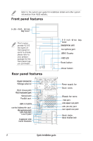
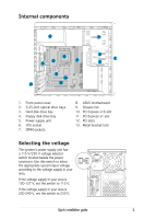
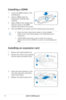
Internal components 5 6 8 9 7 M2V-TVM 11 10 13 12 2 3 1 4 1. Front panel cover 2. 5.25-inch optical drive bays 3. Hard disk drive bay 4. Floppy disk drive bay 5. Power supply unit 6. CPU socket 7. DIMM sockets 8. ASUS motherboard 9. Chassis fan 10. PCI Express x16 slot 11. PCI Express x1 slot 12. PCI slots 13. Metal bracket lock Selecting the voltage The systemʼs power supply unit has a 115 V/230 V voltage selector switch located beside the power connector. Use this switch to select the appropriate system input voltage according to the voltage supply in your area. If the voltage supply in your area is 100-127 V, set the switch to 115 V. If the voltage supply in your area is 200-240 V, set the switch to 230 V. eSATA Quick installation guide 3
-
 1
1 -
 2
2 -
 3
3 -
 4
4 -
 5
5 -
 6
6 -
 7
7 -
 8
8
 |
 |
