Asus p4r800vm Motherboard DIY Troubleshooting Guide - Page 28
Internal connectors
 |
View all Asus p4r800vm manuals
Add to My Manuals
Save this manual to your list of manuals |
Page 28 highlights
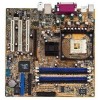
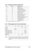
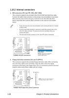
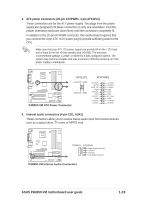
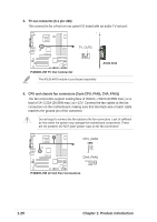
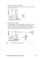
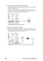
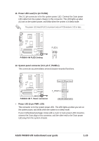
1.10.2 Internal connectors 1. IDE connectors (40-1 pin PRI_IDE1, SEC_IDE1) This connector supports the provided Ultra ATA 100 IDE hard disk drive cable. Connect the cable's blue connector to the primary (recommended) or secondary IDE connector, then connect the gray connector to the Ultra ATA 100 slave device (hard disk drive) and the black connector to the Ultra ATA 100 master device. • Follow the hard disk drive documentation when setting the device in master or slave mode. • Pin 20 on each IDE connector is removed to match the covered hole on the Ultra ATA cable connector. This prevents incorrect orientation when you connect the cables. • The hole near the blue connector on the Ultra ATA cable is intentional. P4R800-VM P4R800-VM IDE Connectors SEC_IDE1 PIN 1 PRI_IDE1 NOTE: Orient the red markings (usually zigzag) on the IDE ribbon cable to PIN 1. 2. Floppy disk drive connector (34-1 pin FLOPPY1) This connector supports the provided floppy disk drive cable. After connecting one end of the cable to this connector, insert the other end to the signal connector at the back of the floppy drive. (Pin 5 is removed to prevent incorrect insertion when using ribbon cables with pin 5 plug). FLOPPY1 P4R800-VM NOTE: Orient the red markings on the floppy ribbon cable to PIN 1. PIN 1 P4R800-VM Floppy Disk Drive Connector 1-18 Chapter 1: Product introduction
-
 1
1 -
2
-
3
-
4
-
5
-
6
-
7
-
8
-
9
-
10
-
11
-
12
-
13
-
14
-
15
-
16
-
17
-
18
-
19
-
20
-
21
-
22
-
 23
23 -
 24
24 -
 25
25 -
 26
26 -
 27
27 -
 28
28 -
 29
29 -
 30
30 -
 31
31 -
 32
32 -
 33
33 -
34
-
35
-
36
-
37
-
38
-
39
-
40
-
41
-
42
-
43
-
44
-
45
-
46
-
47
-
48
-
49
-
50
-
51
-
52
-
53
-
54
-
55
-
56
-
57
-
58
-
59
-
60
-
61
-
62
-
63
-
64
 |
 |