Asus p4s800mx P4S800-MX English User Manual E1447
Asus p4s800mx Manual
 |
View all Asus p4s800mx manuals
Add to My Manuals
Save this manual to your list of manuals |
Asus p4s800mx manual content summary:
- Asus p4s800mx | P4S800-MX English User Manual E1447 - Page 1
Motherboard P4S800-MX User Guide - Asus p4s800mx | P4S800-MX English User Manual E1447 - Page 2
express written permission of ASUSTeK COMPUTER INC. ("ASUS"). Product warranty or service will not be extended if: (1) the ASUS HAS BEEN ADVISED OF THE POSSIBILITY OF SUCH DAMAGES ARISING FROM ANY DEFECT OR ERROR IN THIS MANUAL OR PRODUCT. SPECIFICATIONS AND INFORMATION CONTAINED IN THIS MANUAL - Asus p4s800mx | P4S800-MX English User Manual E1447 - Page 3
v Safety information vi P4S800-MX specification summary vii About this guide viii Chapter 1: Product introduction 1.1 Welcome 1-2 1.2 Package contents 1-2 1.3 Special features 1-2 1.4 Before you proceed 1-5 Onboard LED 1-5 1.5 Motherboard overview 1-6 1.5.1 Motherboard layout - Asus p4s800mx | P4S800-MX English User Manual E1447 - Page 4
2-24 2.5.2 Hardware Monitor 2-25 2.6 Boot Menu 2-26 2.7 Exit Menu 2-28 Chapter 3: Software support 3.1 Install an operating system 3-2 3.2 Support CD information 3-2 3.2.1 Running the support CD 3-2 3.2.2 Drivers menu 3-3 3.2.3 Utilities menu 3-3 3.2.4 ASUS contact information 3-4 iv - Asus p4s800mx | P4S800-MX English User Manual E1447 - Page 5
. This equipment generates, uses and can radiate radio frequency energy and, if not installed and used in accordance with manufacturer's instructions, may cause harmful interference to radio communications. However, there is no guarantee that interference will not occur in a particular installation - Asus p4s800mx | P4S800-MX English User Manual E1447 - Page 6
signal cables from the motherboard, ensure that all service technician or your retailer. Operation safety • Before installing the motherboard and adding devices on it, carefully read all the manuals screws, and staples away from connectors, slots, sockets and circuitry. • Avoid dust, humidity, and - Asus p4s800mx | P4S800-MX English User Manual E1447 - Page 7
P4S800-MX specification summary* CPU Socket 478 for Intel® Pentium® 4 Northwood/Willamette processor Intel® Hyper-Threading technology ready New power design for next generation Intel® Prescott CPU Chipset SiS661 FX SiS963L Front Side Bus (FSB) 800/533/400 MHz Memory 2 x 184-pin DDR DIMM - Asus p4s800mx | P4S800-MX English User Manual E1447 - Page 8
P4S800-MX specification summary BIOS features Industry standard Manageability Form Factor Support CD contents 2Mb Flash EEPROM, DMI, PnP features, SM BIOS 2.3, WfM 2.0, ASUS CrashFree BIOS, ASUS EZ Flash, and ASUS C.P.U. (CPU Parameter Recall) PCI 2.2, USB 2.0/1.1 WOL/WOR by PME, Wake on USB KB/ - Asus p4s800mx | P4S800-MX English User Manual E1447 - Page 9
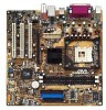
Chapter 1 This chapter describes the features of the motherboard. It includes brief descriptions of the motherboard components, and illustrations of the layout, jumper settings, and connectors. Product introduction - Asus p4s800mx | P4S800-MX English User Manual E1447 - Page 10
Check your P4S800-MX package for the following items. ASUS P4S800-MX motherboard Micro-ATX form factor: 9.6 in x 9.6 in (24.5 cm x 24.5 cm) ASUS P4S800-MX series support CD 80-conductor UltraATA IDE cable Ribbon cable for a 3.5-inch floppy drive I/O shield Bag of extra jumper caps User Guide If any - Asus p4s800mx | P4S800-MX English User Manual E1447 - Page 11
-of-the-art DLS2 MIDI synthesizer with Yamaha DLSbyXG sound set, 5.1 Virtual Theater™ and supports all major game audio technologies including Microsoft DirectX™8.0, Microsoft DirectSound 3D™, A3D, MacroFX, ZoomFX, MultiDrive 5.1 and EAX. See page 1-17. ASUS P4S800-MX motherboard user guide 1-3 - Asus p4s800mx | P4S800-MX English User Manual E1447 - Page 12
The P4S800-MX rear panel is equipped with four (4) Universal Serial Bus (USB) ports to connect USB 2.0 devices. A USB header is also available at mid-board to accommodate a USB module for two (2) additional USB ports. The USB ports and header comply with USB 2.0 specification that supports up - Asus p4s800mx | P4S800-MX English User Manual E1447 - Page 13
you should shut down the system and unplug the power cable before removing or plugging in any motherboard component. The illustration below shows the location of the onboard LED. P4S800-MX P4S800-MX Onboard LED SB_PWR1 ON Standby Power OFF Powered Off ASUS P4S800-MX motherboard user guide 1-5 - Asus p4s800mx | P4S800-MX English User Manual E1447 - Page 14
Motherboard overview 1.5.1 Motherboard layout PS/2KBMS T: Mouse B: Keyboard COM1 KBPWR1 24.5cm (9.6in) Socket 478 CPU_FAN1 Super I/O 2Mb ISA KBPWR1 12 23 +5V (Default) +5VSB P4S800-MX ) 3 2 +5VSB CLRTC1 12 23 Normal (Default) Clear CMOS USBPW56 12 23 +5V (Default) +5VSB PLED1 1 - Asus p4s800mx | P4S800-MX English User Manual E1447 - Page 15
in the image below. 1.5.3 Screw holes Place eight (8) screws into the holes indicated by circles to secure the motherboard to the chassis. Do not overtighten the screws! Doing so may damage the motherboard. Place this side towards the rear of the chassis ASUS P4S800-MX motherboard user guide 1-7 - Asus p4s800mx | P4S800-MX English User Manual E1447 - Page 16
1 that should match a specific corner of the CPU socket. Gold Arrow P4S800-MX Socket 478 Incorrect installation of the CPU into the socket may bend the pins and severely damage the CPU! Notes on Intel® Hyper-Threading Technology 1. Hyper-Threading Technology is supported under Windows XP and Linux - Asus p4s800mx | P4S800-MX English User Manual E1447 - Page 17
the socket lever to secure the CPU. The lever clicks on the side tab to indicate that it is locked. 6. Install a CPU heatsink and fan following the instructions that came with the heatsink package. 7. Connect the CPU fan cable to the CPU_FAN1 connector on the motherboard. Gold Mark ASUS P4S800-MX - Asus p4s800mx | P4S800-MX English User Manual E1447 - Page 18
sockets. P4S800-MX 184-Pin DDR DIMM Sockets Make sure to unplug the power supply before adding or removing DIMMs or other system components. Failure to do so may cause severe damage to both the motherboard and the components. When installing long AGP cards, it is recommended to install the memory - Asus p4s800mx | P4S800-MX English User Manual E1447 - Page 19
socket until the retaining clips snap back in place and the DIMM is properly seated. DDR DIMM notch Unlocked Retaining Clip A DDR DIMM is keyed with a notch so that it fits in only one direction. DO NOT force a DIMM into a socket to avoid damaging the DIMM. ASUS P4S800-MX motherboard user guide - Asus p4s800mx | P4S800-MX English User Manual E1447 - Page 20
and the expansion cards that they support. Make sure to unplug the injury and damage motherboard components. 1.8.1 Installing Remove the system unit cover (if your motherboard is already installed in a chassis). 3. the necessary BIOS settings, if any. See Chapter 2 for information on BIOS setup. 2. - Asus p4s800mx | P4S800-MX English User Manual E1447 - Page 21
-- -- -- -- When using PCI cards on shared slots, ensure that the drivers support "Share IRQ" or that the cards do not need IRQ assignments. Otherwise, conflicts will arise between the two PCI groups, making the system unstable and the card inoperable. ASUS P4S800-MX motherboard user guide 1-13 - Asus p4s800mx | P4S800-MX English User Manual E1447 - Page 22
you ask for one with +1.5V specification. Note the notches on the card golden fingers to ensure that they fit the AGP slot on the motherboard. This motherboard does not support 3.3V AGP cards. Install only +1.5V AGP cards. P4S800-MX Keyed for 1.5v P4S800-MX Accelerated Graphics Port (AGP) 1-14 - Asus p4s800mx | P4S800-MX English User Manual E1447 - Page 23
enter BIOS setup to re-enter data. Except when clearing the RTC RAM, never remove the cap on CLRTC1 jumper default position. Removing the cap will cause system boot failure! P4S800-MX P4S800-MX Clear RTC RAM CLRTC1 12 23 Normal (Default) Clear CMOS ASUS P4S800-MX motherboard user guide 1-15 - Asus p4s800mx | P4S800-MX English User Manual E1447 - Page 24
CPU stopped, DRAM refreshed, system running in low power mode) using the connected USB devices. Set to +5VSB to wake up from S3 sleep mode (no power to CPU mode. P4S800-MX P4S800-MX USB Device Wake BIOS (see 2.5.5 "APM Configuration"). P4S800-MX KBPWR1 12 23 +5V (Default) +5VSB P4S800-MX - Asus p4s800mx | P4S800-MX English User Manual E1447 - Page 25
available for connecting USB 2.0 devices. 9. VGA port. This port connects a VGA compatible monitor. 10. Serial port. This 9-pin COM port is for pointing devices or other serial devices. 11. PS/2 keyboard port. This purple connector is for a PS/2 keyboard. ASUS P4S800-MX motherboard user guide 1-17 - Asus p4s800mx | P4S800-MX English User Manual E1447 - Page 26
markings (usually zigzag) on the IDE ribbon cable to PIN 1. P4S800-MX IDE Connectors PIN 1 2. Floppy disk drive connector (34-1 pin FLOPPY1) This connector supports the provided floppy drive ribbon cable. After connecting one end to the motherboard, connect the other end to the floppy drive. (Pin - Asus p4s800mx | P4S800-MX English User Manual E1447 - Page 27
pin ATXPWR connector, this motherboard requires that you connect the 4-pin ATX +12V power plug to provide sufficient power to the CPU. Make sure that your audio cable. P4S800-MX AGND +5VA BLINE_OUT_R BLINE_OUT_L FP_AUDIO1 P4S800-MX Front Panel Audio Connector ASUS P4S800-MX motherboard user guide - Asus p4s800mx | P4S800-MX English User Manual E1447 - Page 28
GND +12V Rotation P4S800-MX 5. CPU and chassis fan connectors (3-pin CPU_FAN1, CHA_FAN1) The fan connectors support cooling fans of 350mA~740mA (8.88W max.) or a total of 1A~2.22A (26.64W max.) at +12V. Connect the fan cables to the fan connectors on the motherboard, making sure that the black - Asus p4s800mx | P4S800-MX English User Manual E1447 - Page 29
, CD1) These connectors allow you to receive stereo audio input from sound sources such as a CD-ROM, TV tuner, or MPEG card. P4S800-MX AUX1 (White) Left Audio Channel Ground Ground Right Audio Channel CD1 (Black) P4S800-MX Internal Audio Connectors ASUS P4S800-MX motherboard user guide 1-21 - Asus p4s800mx | P4S800-MX English User Manual E1447 - Page 30
hear system beeps and warnings. SPEAKER1 1 P4S800-MX Speaker Out Connector 10. GAME/MIDI connector (16-1 pin GAME1) This connector supports a GAME/ playing or editing audio files. P4S800-MX +5V J2B1 J2CX MIDI_OUT J2CY J2B2 MIDI_IN +5V J1B1 J1CX GND GND J1CY J1B2 +5V P4S800-MX Game Connector - Asus p4s800mx | P4S800-MX English User Manual E1447 - Page 31
when the system is in sleep mode. If your motherboard package comes with a 2-pin to 3-pin power LED converter, connect the 2-pin plug to this connector, and the other end to the 3-pin power LED plug from the system chassis. IDE_LED+ IDE_LED- Ground Reset ASUS P4S800-MX motherboard user guide 1-23 - Asus p4s800mx | P4S800-MX English User Manual E1447 - Page 32
a switch that controls the system power. Pressing the power switch turns the system between ON and SLEEP, or ON and SOFT OFF, depending on the BIOS or OS settings. Pressing the power switch while in the ON mode for more than 4 seconds turns the system OFF. • IDE LED Lead (2-pin IDE_LED - Asus p4s800mx | P4S800-MX English User Manual E1447 - Page 33
Chapter 2 This chapter tells how to change system settings through the BIOS Setup menus. Detailed descriptions of the BIOS parameters are also provided. BIOS information - Asus p4s800mx | P4S800-MX English User Manual E1447 - Page 34
mode.) 3. ASUS CrashFree BIOS (Updates the BIOS using a bootable floppy disk.) 4. ASUS Update (Updates the BIOS in Windows® environment.) Refer to the corresponding section for details on these utilities. Important notes It is recommended that you save a copy of the original motherboard BIOS file to - Asus p4s800mx | P4S800-MX English User Manual E1447 - Page 35
the system while updating the BIOS! Doing so may cause system boot failure! User recovery requested. Starting BIOS recovery... Checking for floppy... Floppy found! Reading file "P4S800MX.BIN". Completed. Start flashing... Flashed successfully. Rebooting. ASUS P4S800-MX motherboard user guide 2-3 - Asus p4s800mx | P4S800-MX English User Manual E1447 - Page 36
DOS mode. Copying the original motherboard BIOS To copy the original motherboard BIOS file: 1. Copy the AFLASH utility from the support CD to the boot disk you created. AFLASH does not work in the DOS prompt within Windows®, and does not work with certain memory drivers that may be loaded when you - Asus p4s800mx | P4S800-MX English User Manual E1447 - Page 37
the update. 7. The utility starts updating the BIOS. The boot block is automatically updated only when necessary. This minimizes the possibility of boot problems in case of update failures. When updating is done, the message "Flashed Successfully" appears. ASUS P4S800-MX motherboard user guide - Asus p4s800mx | P4S800-MX English User Manual E1447 - Page 38
cause boot problems. Just repeat the process, and if the problem persists, load the original BIOS file you saved to the boot disk. If the Flash Memory Writer utility is not able to successfully update a complete BIOS file, the system may not boot. If this happens, call the ASUS Technical Support for - Asus p4s800mx | P4S800-MX English User Manual E1447 - Page 39
system. To update the BIOS using the ASUS Update: 1. Launch the utility from the Windows desktop by clicking Start > Programs > ASUS > ASUSUpdate > ASUSUpdate. The ASUS Update initial screen appears. 2. Select your desired update method, then click Next. ASUS P4S800-MX motherboard user guide 2-7 - Asus p4s800mx | P4S800-MX English User Manual E1447 - Page 40
. Click Next. 4. From the FTP site, select the BIOS version that you wish to download. Click Next. 5. Follow the instructions on the succeeding screens to complete the update process. If you selected the option to update the BIOS from a file, a window pops up prompting you to locate the file. Select - Asus p4s800mx | P4S800-MX English User Manual E1447 - Page 41
default system device used to locate and load the Operating System. Use this menu to exit the current menu or to exit the Setup program. To access the menu bar items, press the right or left arrow key on the keyboard until the desired item is highlighted. ASUS P4S800-MX motherboard user guide 2-9 - Asus p4s800mx | P4S800-MX English User Manual E1447 - Page 42
Defaults Saves changes and exits Setup General help In addition to the Item Specific Help window, the BIOS setup program also provides a General Help screen. You may launch this screen from any menu by simply pressing or the + combination. The General Help screen lists the - Asus p4s800mx | P4S800-MX English User Manual E1447 - Page 43
appear in the Item Specific Help window located to the right of each menu. This window displays the help text for the currently highlighted field. 2.3 Main Menu When you enter the > or + keys to move between the month, day, and year fields. ASUS P4S800-MX motherboard user guide 2-11 - Asus p4s800mx | P4S800-MX English User Manual E1447 - Page 44
, the Supervisor password is required to enter the BIOS Setup program and to gain full access to the configuration fields. Forgot the password? If you forget your password, you can clear it by erasing the CMOS Real Time Clock (RTC) RAM. The RAM data containing the password information is powered by - Asus p4s800mx | P4S800-MX English User Manual E1447 - Page 45
values for the remaining fields on this sub-menu. If automatic detection fails, this may be because Manually enter the number of cylinders, heads and sectors per track for the drive. Refer to the drive documentation or on the drive label for this information. ASUS P4S800-MX motherboard user guide - Asus p4s800mx | P4S800-MX English User Manual E1447 - Page 46
making your selections on this sub-menu, press the key to return to the Main menu. When the Main menu appears, the hard disk drive field Translation Method field to [Manual]. CHS Capacity This field shows the drive's maximum CHS capacity as calculated by the BIOS based on the drive information - Asus p4s800mx | P4S800-MX English User Manual E1447 - Page 47
field to [User Type HDD]. Configuration options: [0] [1] [2] [3] [4] [5] [6] [Disabled] 2.3.2 Keyboard Features Boot Up NumLock Status [On] This field enables users to activate the Number Lock function upon system boot. Configuration options: [Off] [On] ASUS P4S800-MX motherboard user guide 2-15 - Asus p4s800mx | P4S800-MX English User Manual E1447 - Page 48
] [1/2 Sec] [3/4 Sec] [1 Sec] 2.4 Advanced Menu CPU Speed [Manual] When the motherboard is set to JumperFree™ mode, this field allows you cannot change the setting of this item. CPU External Frequency (MHz) (when CPU Speed is set to [Manual]) This feature tells the clock generator what frequency - Asus p4s800mx | P4S800-MX English User Manual E1447 - Page 49
] OS/2 Onboard Memory > 64M [Disabled] When using OS/2 operating systems with installed DRAM of greater than 64MB, you need to set this option to [Enabled]. Otherwise, leave to the default setting [Disabled]. Configuration options: [Disabled] [Enabled] ASUS P4S800-MX motherboard user guide 2-17 - Asus p4s800mx | P4S800-MX English User Manual E1447 - Page 50
the optimal timings for items 2-5, depending on the memory modules that you are using. The default setting The EEPROM on the memory module stores critical information about the module, such as memory type, size, is coordinated with the CPU frequency. When set to [Asynchronous], AGP/PCI frequency - Asus p4s800mx | P4S800-MX English User Manual E1447 - Page 51
set both channels to [Disabled]. Configuration options: [Both] [Primary] [Secondary] [Disabled] IDE Bus Master Support [Enabled] This item controls the IDE Bus Master support for non-Windows operating systems. Configuration options: [Enabled] [Disabled] ASUS P4S800-MX motherboard user guide 2-19 - Asus p4s800mx | P4S800-MX English User Manual E1447 - Page 52
] [200H-207H] [208H-20FH] Onboard MIDI I/O [Disabled] This field sets the I/O address for the MIDI I/O port. Configuration options: [Disabled] [330H-331H] [300H-301H] 2-20 Chapter 2: BIOS information - Asus p4s800mx | P4S800-MX English User Manual E1447 - Page 53
show colors properly. Setting this field to [Enabled] corrects this problem. If you are using standard VGA cards, leave this field to USB Function [Enabled] This field allows you to enable or disable the USB function. Configuration options: [Enabled] [Disabled] ASUS P4S800-MX motherboard user guide - Asus p4s800mx | P4S800-MX English User Manual E1447 - Page 54
[Disabled] This field allows you enable or disable the onboard LAN Boot ROM feature. Configuration options: [Disabled] [Enabled] Onboard AC97 Audio Controller [Auto] This field allows you to disable the onboard AC97 audio controller or set to the default [Auto] for optimum performance. Configuration - Asus p4s800mx | P4S800-MX English User Manual E1447 - Page 55
No/ICU] [Yes] 2.5 Power Menu The Power menu allows you to reduce power consumption. BIOS to control the video display card if it supports the DPMS feature. [Blank Screen] only blanks the screen. Use this for monitors without power management or "green" features. ASUS P4S800-MX motherboard user guide - Asus p4s800mx | P4S800-MX English User Manual E1447 - Page 56
] ACPI Suspend To RAM [Disabled] This field allows you to enable or disable the ACPI Suspend-to-RAM feature. To support this feature, the for less than 4 seconds. [Suspend] allows the button to have a dual function where pressing less than 4 seconds puts the system in sleep mode 2: BIOS information - Asus p4s800mx | P4S800-MX English User Manual E1447 - Page 57
a PCI LAN or modem card to use specific keys on CPU Temperature MB Temperature The onboard hardware monitor automatically detects and displays the motherboard and CPU temperatures. Select [Ignore] to disable the MB or CPU temperature auto-detect function. ASUS P4S800-MX motherboard user guide - Asus p4s800mx | P4S800-MX English User Manual E1447 - Page 58
CPU, chassis, and power fan speeds in rotations per minute (RPM). If any of the fans is not connected to the motherboard, the specific or DEL to enter SETUP". 2.6 Boot Menu Boot Sequence The Boot menu allows you to select among the four possible types of boot devices listed using the up and down - Asus p4s800mx | P4S800-MX English User Manual E1447 - Page 59
second, third, and fourth time. Configuration options: [Enabled] [Disabled] Boot Up Floppy Seek [Enabled] When enabled, the BIOS will seek the floppy disk drive to determine whether the drive has 40 the 16 IRQs only. Configuration options: [APIC] [PIC] ASUS P4S800-MX motherboard user guide 2-27 - Asus p4s800mx | P4S800-MX English User Manual E1447 - Page 60
your selections, choose this option from the Exit menu to ensure the values you selected are saved to the CMOS RAM. The CMOS RAM is sustained by an onboard backup battery and , a confirmation window appears. Select [Yes] to save changes to the non-volatile RAM. 2-28 Chapter 2: BIOS information - Asus p4s800mx | P4S800-MX English User Manual E1447 - Page 61
Chapter 3 This chapter describes the contents of the support CD that comes with the motherboard package. Software support - Asus p4s800mx | P4S800-MX English User Manual E1447 - Page 62
the motherboard features. The contents of the support CD are subject to change at any time without notice. Visit the ASUS website for updates. 3.2.1 Running the support CD To begin using the support CD, simply insert the CD into your CD-ROM drive. The CD automatically displays the Drivers menu if - Asus p4s800mx | P4S800-MX English User Manual E1447 - Page 63
audio driver and SoundMAX application. SiS PCI LAN Driver This item installs the driver for the onboard SiS PCI LAN controller. USB 1.1 Driver This item installs the USB 1.1 driver. 3.2.3 Utilities menu The Utilities menu shows the applications and other software that the motherboard supports. ASUS - Asus p4s800mx | P4S800-MX English User Manual E1447 - Page 64
This program allows you to download the latest version of the BIOS from the ASUS website. Before using the ASUS Update, make sure that you have an Internet connection so you can connect to the ASUS website. See page 2-7 for ASUS Update installation and use. Microsoft® DirectX 8.1 This item installs
-
 1
1 -
 2
2 -
 3
3 -
 4
4 -
 5
5 -
 6
6 -
 7
7 -
8
-
9
-
10
-
11
-
12
-
13
-
14
-
15
-
16
-
17
-
18
-
19
-
20
-
21
-
22
-
23
-
24
-
25
-
26
-
27
-
28
-
29
-
30
-
31
-
32
-
33
-
34
-
35
-
36
-
37
-
38
-
39
-
40
-
41
-
42
-
43
-
44
-
45
-
46
-
47
-
48
-
49
-
50
-
51
-
52
-
53
-
54
-
55
-
56
-
57
-
58
-
59
-
60
-
61
-
62
-
63
-
64
 |
 |

Motherboard
P4S800-MX
User Guide