Behringer 121 DUAL VCF Quick Start Guide - Page 1
Behringer 121 DUAL VCF Manual
 |
View all Behringer 121 DUAL VCF manuals
Add to My Manuals
Save this manual to your list of manuals |
Page 1 highlights
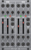
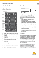
Quick Start Guide 121 DUAL VCF Legendary Analog Dual VCF Module for Eurorack Controls Power Connection (1) The module comes with the required power cable for connecting to a standard Eurorack power supply system. Follow these steps to connect power to the module. It is easier to make (2) these connections before the module has been mounted into a rack case. (3) 1. Turn the power supply or rack case power off and disconnect the power cable. (4) 2. Insert the 16-pin connector on the power cable into the socket on the power supply or rack case. The connector has (5) a tab that will align with the gap in the socket, so it cannot be inserted incorrectly. If the power supply does not have (6) a keyed socket, be sure to orient pin 1 (-12 V) with the red stripe on the cable. (7) 3. Insert the 10-pin connector into the socket on the back of the module. The connector has a tab that will align with the socket for correct orientation. (8) 4. After both ends of the power cable have been securely attached, you may mount the module in a case and turn on the power supply. (1) SIG IN - Connect incoming signals via 3.5 mm TS cable. Installation (2) SIG LEVEL - Adjust the level of the signals connected to the inputs. The necessary screws are included with the module for mounting (3) VCF OUT - Send the VCF signal to other modules via in a Eurorack case. Connect the power cable before mounting. 3.5 mm TS cable. Depending on the rack case, there may be a series of fixed holes (4) RES - Boosts the resonance frequencies selected with the CUTOFF slider, potentially causing VCF oscillation. spaced 2 HP apart along the length of the case, or a track that allows individual threaded plates to slide along the length of the case. The free-moving threaded plates allow precise (5) CUTOFF - Adjust the cutoff frequency of the positioning of the module, but each plate should be positioned in low-pass filter. the approximate relation to the mounting holes in your module (6) FIXED HPF - Adjust the high-pass filter from OFF, before attaching the screws. 1 (1 kHz), 2 (2 kHz), or 3 (5 kHz). . Hold the module against the Eurorack rails so that each of the (7) MOD LEVEL - Attenuate the voltage connected to the associated MOD IN jack. mounting holes are aligned with a threaded rail or threaded plate. Attach the screws part way to start, which will allow small adjustments to the positioning while you get them all (8) MOD IN - Connect a voltage that controls the aligned. After the final position has been established, tighten the VCF LPF frequency. screws down.
-
 1
1 -
 2
2
 |
 |
