Behringer 172 PHASE SHIFTER/DELAY/LFO Quick Start Guide
Behringer 172 PHASE SHIFTER/DELAY/LFO Manual
 |
View all Behringer 172 PHASE SHIFTER/DELAY/LFO manuals
Add to My Manuals
Save this manual to your list of manuals |
Behringer 172 PHASE SHIFTER/DELAY/LFO manual content summary:
- Behringer 172 PHASE SHIFTER/DELAY/LFO | Quick Start Guide - Page 1
Quick Start Guide SYSTEM 100 172 PHASE SHIFTER/ DELAY/LFO Legendary Analog Phase Shifter/ Delay/LFO Module for Eurorack Controls (3) (4) (5) (6) (1) (2) (7) (7) RESONANCE - Adjusts the amount of signal that is - Behringer 172 PHASE SHIFTER/DELAY/LFO | Quick Start Guide - Page 2
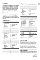
Installation The necessary screws are included with the module for mounting in a Eurorack case. Connect the power cable before mounting. Depending on the rack case, there may be a series of fixed holes spaced 2 HP apart along the length of the case, or a track that allows individual threaded plates
-
 1
1 -
 2
2
 |
 |
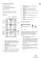
Quick Start Guide
SYSTEM 100
172 PHASE SHIFTER/
DELAY/LFO
Legendary Analog Phase Shifter/
Delay/LFO Module for Eurorack
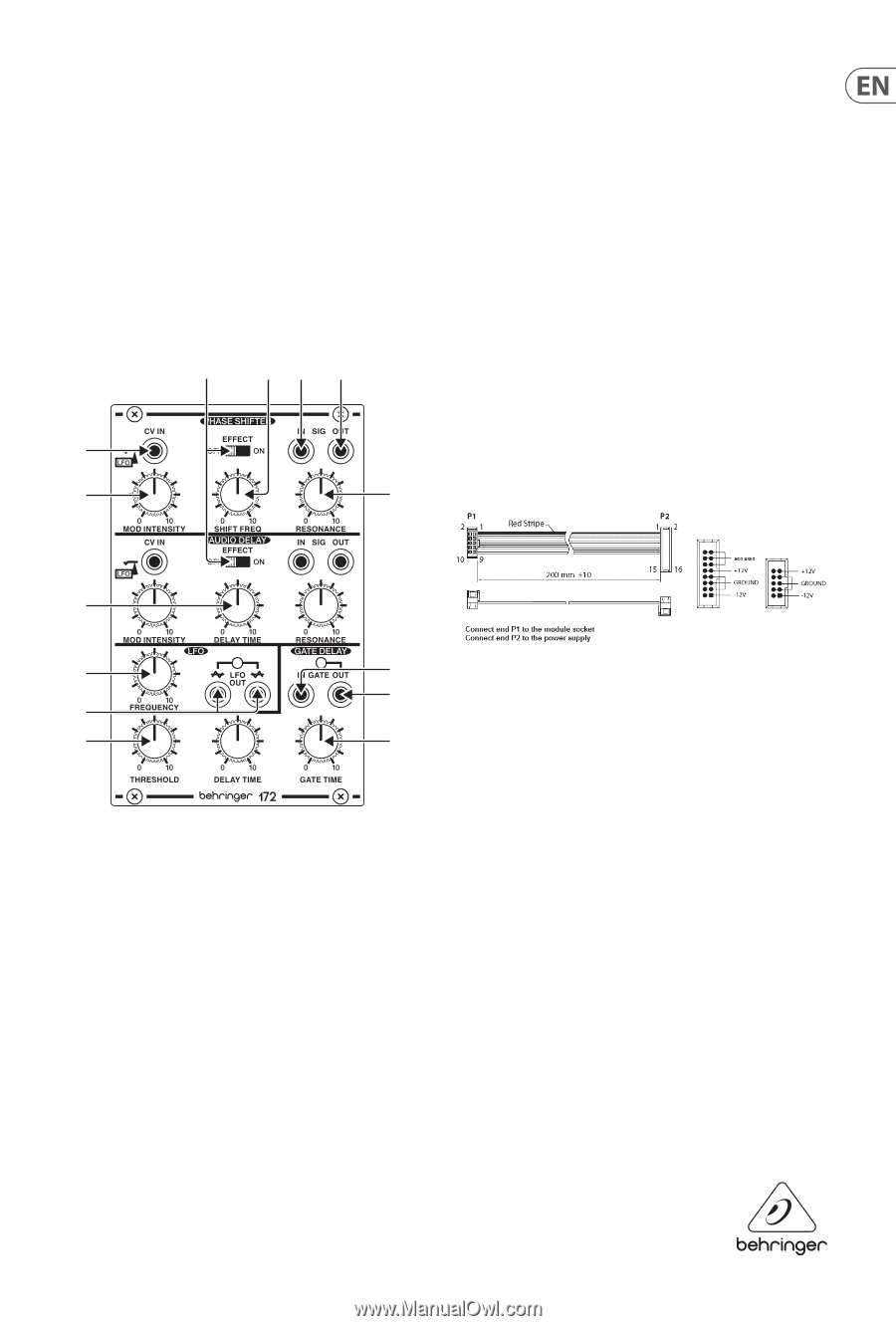
Controls
(1)
CV IN
– Accepts voltage from an external source to
control or modulate the phase shifter frequency or audio
delay time. If no jack is inserted the LFO can be used to
modulate the effect.
(2)
MOD INTENSITY
– Controls how much the effect is
modulated by the LFO or external CV input.
(3)
EFFECT ON/OFF
– Engages or disengages the
effect section.
(4)
SHIFT FREQ
– Adjusts the frequency of the phase shifter.
(5)
SIG IN
– Accepts an incoming signal via 3.5 mm TS cable.
(6)
SIG OUT
– Sends the signal from the effect section.
(7)
RESONANCE
– Adjusts the amount of signal that is fed
back through the effect.
(8)
DELAY TIME
– Adjusts the time of the delay effect.
(9)
FREQUENCY
– Controls the LFO output frequency.
(10)
LFO OUT
– Sends the LFO signal as a triangle and inverted
triangle wave.
(11)
THRESHOLD
– Controls the input voltage level required to
trigger the gate.
(12)
GATE IN
– Accepts an incoming gate signal via 3.5 mm
TS cable.
(13)
GATE OUT
– Send the gate delay signal via 3.5 mm
TS cable.
(14)
GATE TIME
– Controls the gate length.
Power Connection
The module comes with the required power cable for connecting
to a standard Eurorack power supply system. Follow these
steps to connect power to the module. It is easier to make
these connections before the module has been mounted into
a rack case.
1.
Turn the power supply or rack case power off and
disconnect the power cable.
2.
Insert the 16-pin connector on the power cable into the
socket on the power supply or rack case. The connector has
a tab that will align with the gap in the socket, so it cannot
be inserted incorrectly. If the power supply does not have
a keyed socket, be sure to orient pin 1 (-12 V) with the red
stripe on the cable.
3.
Insert the 10-pin connector into the socket on the back of
the module. The connector has a tab that will align with the
socket for correct orientation.
4.
After both ends of the power cable have been securely
attached, you may mount the module in a case and turn on
the power supply.
(1)
(2)
(8)
(6)
(5)
(4)
(11)
(14)
(7)
(13)
(9)
(10)
(3)
(12)