Behringer 904A VOLTAGE CONTROLLED LOW PASS FILTER Quick Start Guide - Page 1
Behringer 904A VOLTAGE CONTROLLED LOW PASS FILTER Manual
 |
View all Behringer 904A VOLTAGE CONTROLLED LOW PASS FILTER manuals
Add to My Manuals
Save this manual to your list of manuals |
Page 1 highlights
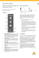
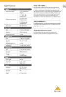
Quick Start Guide 904A VOLTAGE CONTROLLED Power Connection LOW PASS FILTER Legendary Analog Low Pass VCF Module for Eurorack Controls The 904A comes with the required power cable for connecting to a standard Eurorack power supply system. Follow these steps to connect power to the module. It is easier to make (1) these connections before the module has been mounted into a rack case. 1. Turn the power supply or rack case power off and disconnect the power cable. (2) 2. Insert the 16-pin connector on the power cable into the socket on the power supply or rack case. The connector has a tab that will align with the gap in the socket, so it cannot be inserted incorrectly. If the power supply does not have a keyed socket, be sure to orient pin 1 (-12 V) with the red (3) stripe on the cable. 3. Insert the 10-pin connector into the socket on the back of the module. The connector has a tab that will align with the (4) (5) socket for correct orientation. 4. After both ends of the power cable have been securely attached, you may mount the module in a case and turn on (6) the power supply. (1) FIXED CONTROL VOLTAGE - Also referred to as "cutoff Installation frequency", this knob manually determines the frequency above which frequencies are attenuated. The resulting The necessary screws are included with the module for mounting frequency will depend on this knob's setting as well as in a Eurorack case. Connect the power cable before mounting. voltage received from the control inputs. Depending on the rack case, there may be a series of fixed holes (2) FREQUENCY RANGE - Select one of 3 frequency bands spaced 2 HP apart along the length of the case, or a track that in which the fixed control voltage operates. Position 1 is allows individual threaded plates to slide along the length 1 Hz to 5 kHz, position 2 is 4 Hz to 20 kHz, and position 3 is of the case. The free-moving threaded plates allow precise 16 Hz to 80 kHz. positioning of the module, but each plate should be positioned in (3) REGENERATION - This knob varies the amount of internal feedback, creating a resonant peak at the cutoff the approximate relation to the mounting holes in your module before attaching the screws. frequency. At higher settings this becomes self-oscillation. Hold the module against the Eurorack rails so that each of the (4) SIGNAL INPUT - Connect the incoming signal via 3.5 mm TS cable. mounting holes are aligned with a threaded rail or threaded plate. Attach the screws part way to start, which will allow small adjustments to the positioning while you get them all (5) SIGNAL OUTPUT - Send the processed signal to another aligned. After the final position has been established, tighten the module via 3.5 mm TS cable. screws down. (6) CONTROL INPUTS - Connect control voltage signals from other modules to affect the cutoff frequency. The sum of the voltage received doubles the frequency cutoff point for each 1 V increase.
-
 1
1 -
 2
2
 |
 |