Behringer 921A OSCILLATOR DRIVER Quick Start Guide - Page 1
Behringer 921A OSCILLATOR DRIVER Manual
 |
View all Behringer 921A OSCILLATOR DRIVER manuals
Add to My Manuals
Save this manual to your list of manuals |
Page 1 highlights
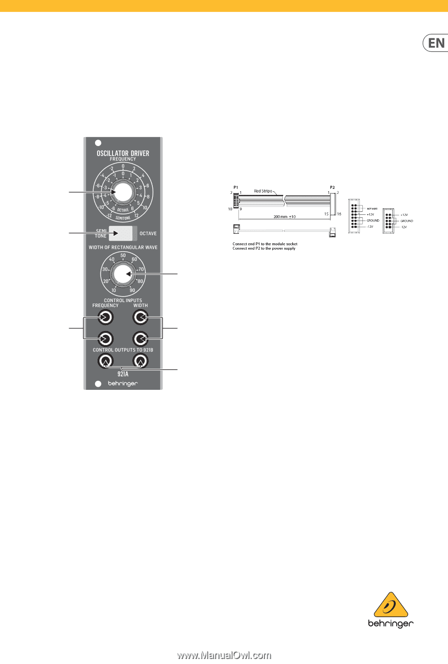
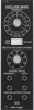
Quick Start Guide 921A OSCILLATOR DRIVER Legendary Analog Oscillator Driver Module for Eurorack Controls (1) (6) CONTROL OUTPUTS TO 921B - Connect control signals to a 921B VCO modules. The left output jack is for frequency control signals and connects to one of the 921B frequency link jacks. The right output jack is for rectangular wave width control signals and connects to one of the 921B width link jacks. The secondary parallel link jacks on the 921B can then be chained to other 921B VCO modules, and up to twelve 921B modules can be driven by the 921A driver. Power Connection (2) (3) The 921A OSCILLATOR DRIVER module comes with the required power cable for connecting to a standard Eurorack power supply system. Follow these steps to connect power to the module. It is easier to make these connections before the module has been mounted into a rack case. (4) (5) 1. Turn the power supply or rack case power off and disconnect the power cable. (6) (1) FREQUENCY - This knob manually sets the frequency for oscillators connected to the 921A module. (2) SEMITONE/OCTAVE - Use this rocker switch to select between semitone or octave increments for the FREQUENCY knob. (3) WIDTH OF RECTANGULAR WAVE - Select between settings ranging from 10% to 90%. 2. Insert the 16-pin connector on the power cable into the socket on the power supply or rack case. The connector has a tab that will align with the gap in the socket, so it cannot be inserted incorrectly. If the power supply does not have a keyed socket, be sure to orient pin 1 (-12 V) with the red stripe on the cable. 3. Insert the 10-pin connector into the socket on the back of the module. The connector has a tab that will align with the socket for correct orientation. 4. After both ends of the power cable have been securely attached, you may mount the module in a case and turn on the power supply. (4) CONTROL INPUT/FREQUENCY - Connect incoming control voltage signals for the frequency to these dual summed input jacks via cables with 3.5 mm TS connectors. These two control inputs are also summed with the FREQUENCY control knob. (5) CONTROL INPUTS/WIDTH - Connect incoming control voltage/modulation signals for the rectangular wave width to these dual summed jacks via cables with 3.5 mm TS connectors. These two control inputs are also summed with the WIDTH knobs.
-
 1
1 -
 2
2
 |
 |