Behringer 921B OSCILLATOR Quick Start Guide - Page 1
Behringer 921B OSCILLATOR Manual
 |
View all Behringer 921B OSCILLATOR manuals
Add to My Manuals
Save this manual to your list of manuals |
Page 1 highlights
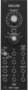
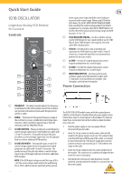
Quick Start Guide 921B OSCILLATOR Legendary Analog VCO Module for Eurorack Controls (1) (2) (5) (3) (6) (9) (7) (4) (8) at the square wave output until the control voltage is returned to the normal range. When using 921B with a 921A driver, the 921A's WIDTH OF RECTANGULAR WAVE knob can offset the control voltage output from 921A to compensate. For example, when 921A's WIDTH knob is set to 50%, the 921A's normal control voltage range into 921B becomes -3 V to +3 V. (5) SYNC WEAK/OFF/STRONG - Use this switch to set how closely 921B follows the sync signal routed in via the SYNC IN jack. If the SYNC IN input is not required, select the center OFF switch position. (6) SYNC IN - Use this jack to route an external sync signal into the 921B module via cables with 3.5 mm TS connectors. A sawtooth waveform is recommended to produce the best sync results. (7) AC MOD - Use this AC-coupled input jack to control frequency modulation via a control signal. (8) DC MOD - Use this DC-coupled input jack to control frequency modulation via a control signal. (9) WAVEFORM OUTPUTS - Use these jacks to route oscillator signals out of the module via cables with 3.5 mm jacks. Four waveforms are available: sine, triangular, sawtooth and rectangular. Power Connection (1) FREQUENCY - This knob manually adjusts the frequency in semitones for the 921B oscillator circuit. This oscillator can generate both audio and sub-audio frequencies for control or audio. The 921B OSCILLATOR module comes with the required power cable for connecting to a standard Eurorack power supply system. (2) RANGE - This knob sets the general frequency range of Follow these steps to connect power to the module. It is easier to the oscillator in octaves, numbered to match pipe organ make these connections before the module has been mounted notations, which can then be adjusted up or down by into a rack case. semitones with the FREQUENCY knob. 1. Turn the power supply or rack case power off and (3) 921AB LINK FREQ - These parallel jacks accept frequency disconnect the power cable. control voltage signals from a 921A module via cables with 3.5 mm TS connectors. The parallel wiring of the jacks also allows a control voltage signal to be sent through and back out to drive additional 921B modules. 2. Insert the 16-pin connector on the power cable into the socket on the power supply or rack case. The connector has a tab that will align with the gap in the socket, so it cannot be inserted incorrectly. If the power supply does not have (4) 921AB LINK WIDTH - These parallel jacks accept 921A a keyed socket, be sure to orient pin 1 (-12 V) with the red control voltage signals for the rectangular wave width stripe on the cable. parameter via cables with 3.5 mm TS connectors. The parallel wiring of the jacks also allows a control voltage signal to be sent through and back out to drive additional 921B modules. 3. Insert the 10-pin connector into the socket on the back of the module. The connector has a tab that will align with the socket for correct orientation. NOTE: If the 921B input voltage exceeds the range of 0 to +6 V, the excess voltage could result in the width being 0% or 100%, which means no waveform will be present 4. After both ends of the power cable have been securely attached, you may mount the module in a case and turn on the power supply. V 1.0
-
 1
1 -
 2
2 -
 3
3
 |
 |