Behringer 960 SEQUENTIAL CONTROLLER Quick Start Guide - Page 2
Power Connection, Installation, Specifications - manual
 |
View all Behringer 960 SEQUENTIAL CONTROLLER manuals
Add to My Manuals
Save this manual to your list of manuals |
Page 2 highlights
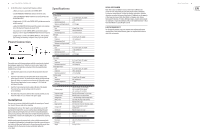
2 960 SEQUENTIAL CONTROLLER 6. Set the 960 oscillator's maximum high frequency as follows: a. Make sure no jack is connected to the CONTROL INPUT. b. Set the FREQUENCY VERNIER fully clockwise (10 on the scale). c. Adjust the FREQUENCY ADJUST trimmer to set exactly 500 Hz at the OSCILLATOR OUTPUT. d. Apply exactly +2.0 VDC to the CONTROL INPUT jack (this may stop the oscillator running). e. Adjust the FREQ STOP ADJ trimmer until the oscillator starts running and set the maximum frequency to around 550 Hz. f. Disconnect the +2.0 VDC CONTROL INPUT and check the oscillator frequency is 500 Hz. Adjust the FREQUENCY ADJUST trimmer if required. g. Apply exactly +2.0 VDC to the CONTROL INPUT jack, if the oscillator stays running, the trimming is completed. If not, repeat as required. Power Connection The module comes with the required power cable for connecting to a standard Eurorack power supply system. Follow these steps to connect power to the module. It is easier to make these connections before the module has been mounted into a rack case. 1. Turn the power supply or rack case power off and disconnect the power cable. 2. Insert the 16-pin connector on the power cable into the socket on the power supply or rack case. The connector has a tab that will align with the gap in the socket, so it cannot be inserted incorrectly. If the power supply does not have a keyed socket, be sure to orient pin 1 (-12 V) with the red stripe on the cable. 3. Insert the 10-pin connector into the socket on the back of the module. The connector has a tab that will align with the socket for correct orientation. 4. After both ends of the power cable have been securely attached, you may mount the module in a case and turn on the power supply. Installation The necessary screws are included with the module for mounting in a Eurorack case. Connect the power cable before mounting. Depending on the rack case, there may be a series of fixed holes spaced 2 HP apart along the length of the case, or a track that allows individual threaded plates to slide along the length of the case. The free-moving threaded plates allow precise positioning of the module, but each plate should be positioned in the approximate relation to the mounting holes in your module before attaching the screws. Hold the module against the Eurorack rails so that each of the mounting holes are aligned with a threaded rail or threaded plate. Attach the screws part way to start, which will allow small adjustments to the positioning while you get them all aligned. After the final position has been established, tighten the screws down. Specifications Inputs Oscillator on/off Type Impedance Maximum input level Minimum switching threshold Control input Type Impedance Maximum input level Shift input Type Impedance Maximum input level Minimum switching threshold Stage triggers Type Impedance Maximum input level Minimum switching threshold Outputs Row outputs Type Impedance Maximum output level Stage trigger outputs Type Impedance Maximum output level Oscillator output Type Impedance Maximum output level Duty cycle Controls Frequency range Frequency vernier Oscillator on/off Voltage knobs Mode switch Set Range switches Timing on/off Shift button Power Power supply Current draw Physical Dimensions Rack units Weight 2 x 3.5 mm TS jacks, AC coupled >3 kΩ, unbalanced +5 V +3.5 V trigger 3.5 mm TS jack, 1 V/oct 100 kΩ, unbalanced ±2 V, vernier set to 5 3.5 mm TS jack, DC coupled 7 kΩ, unbalanced ±5 V +1.5 V 8 x 3.5 mm TS jacks, AC coupled >3 kΩ, unbalanced +5 V +3.5 V trigger 6 x 3.5 mm TS jacks, DC coupled 500 Ω, unbalanced +8 V (range X4) 8 x 3.5 mm TS jacks, DC coupled 250 Ω, unbalanced +5 V, active high 3.5 mm TS jack, DC coupled 4 kΩ, unbalanced +4 dBu 90% 1 (0.04 to 0.5 Hz), 2 (2.75 to 30 Hz) 3 (0.17 to 2 Hz), 4 (11 to 130 Hz) 5 (0.7 to 8 Hz), 6 (44 to 500 Hz) Tune the oscillator range, 3 octave range Manually start or stop the oscillator -∞ to max voltage set by the range switch Skip stage, play stage, stop sequencer Manually select stage X1 (+2 V), X2 (+4 V), X4 (+8 V) max. output Allows 3rd row knobs to control stage duration Manually skip to next stage Eurorack 100 mA (+12 V), 50 mA (-12 V) 284 x 129 x 47 mm (11.2 x 5.1 x 1.9") 56 HP 0.64 kg (1.41 lbs) LEGAL DISCLAIMER Music Tribe accepts no liability for any loss which may be suffered by any person who relies either wholly or in part upon any description, photograph, or statement contained herein. Technical specifications, appearances and other information are subject to change without notice. All trademarks are the property of their respective owners. Midas, Klark Teknik, Lab Gruppen, Lake, Tannoy, Turbosound, TC Electronic, TC Helicon, Behringer, Bugera, Auratone and Coolaudio are trademarks or registered trademarks of Music Tribe Global Brands Ltd. © Music Tribe Global Brands Ltd. 2020 All rights reserved. LIMITED WARRANTY For the applicable warranty terms and conditions and additional information regarding Music Tribe's Limited Warranty, please see complete details online at musictribe.com/warranty. Quick Start Guide 3
-
 1
1 -
 2
2 -
 3
3
 |
 |
