Behringer DEQ1024 Manual - Page 4
Introduction, Control Elements - ultragraph digital feedback destroyer
 |
View all Behringer DEQ1024 manuals
Add to My Manuals
Save this manual to your list of manuals |
Page 4 highlights
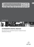
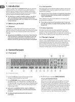
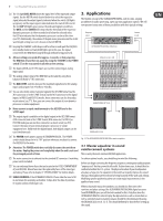
4 ULTRAGRAPH DIGITAL DEQ1024 1. Introduction In addition to graphic EQing, the ULTRAGRAPH DIGITAL gives you a wide array of additional functions, such as feedback destroyer, pink noise generator, limiter/noise gate etc., leaving no wishes open. With these and many more features the DEQ1024 is an absolutely all-purpose device for your recording or mastering studio and will definitely upgrade your equipment. ◊ The following user's manual is intended to familiarize you with the unit's control elements, so that you can master all the functions. After having thoroughly read the user's manual, store it at a safe place for future reference. 1.1 Before you get started 1.1.1 Shipment The DEQ1024 was carefully packed at the factory to assure secure transport. Should the condition of the cardboard box suggest that damage may have taken place, please inspect the unit immediately and look for physical indications of damage. ◊ Damaged units should NEVER be sent directly to us. Please inform the dealer from whom you acquired the unit immediately as well as the transportation company from which you took delivery of the unit. Otherwise, all claims for replacement/repair may be rendered invalid. 1.1.2 Initial operation Please make sure the unit is provided with sufficient ventilation, and never place the ULTRAGRAPH DIGITAL on top of an amplifier or in the vicinity of a heater to avoid the risk of overheating. ◊ Faulty fuses must be replaced with fuses of appropriate rating without exception! The correct value of the fuses needed can be found in the chapter "SPECIFICATIONS". Power is delivered via the cable enclosed with the unit. All requiered safety precautions have been adhered to. ◊ Please make sure that the unit is grounded at all times. For your own protection, you should never tamper with the grounding of the cable or the unit itself. 1.1.3 Online registration Please take a few minutes and send us the completely filled out warranty card within 14 days of the date of purchase. You may also register online at behringer.com. The serial number needed for the registration is located at the top of the unit. Failure to register your product may void future warranty claims. 1.2 The user's manual The user's manual is designed to give you both an overview of the control elements, as well as detailed information on how to use them. In order to help you understand the links between the controls, we have arranged them in groups according to their function. If you need to know more about specific issues, please visit our website at behringer.com, where you'll find additional information on mixing consoles, effects units and dynamic processors. 2. Control Elements 2.1 Front panel (1) (12) (8) (9) (14) (2) Fig. 2.1: Front panel control elements (3) (4) (5) (6) (7) (11) (13) (10) (1) Use the 45-mm EQ faders to increase or decrease any one of the 31 frequency bands. Each fader has its own red LED. (2) Use the FADER RANGE switches to regulate increasing/decreasing in three different levels: +12/-12 dB (green LED), +6/-6 dB (green LED) and 0/-24 dB (yellow LED). The last option is well suited for eliminating feedback frequencies, since you can select a very pronounced lowering of a specific frequency range (-24 dB). ◊ Each switch on your DEQ1024 (with the exception of CONFIG and CLOCK) has its own LED that lights up when the respective function is activated. ◊ All settings you implement always affect both channels of your DEQ1024. (3) The DEQ1024 features an automatic FEEDBACK DESTROYER. Activating the FEEDBACK DESTROYER: When you press the ON/OFF switch (yellow LED lights up), the feedback destroyer scans the audio signal for feedback frequencies. As soon as one or more frequencies show feedback, the red LED of the RESET (HOLD) switch lights up. The affected frequencies are then automatically lowered. In addition, your audio program is constantly scanned for new feedback frequencies, and feedback is destroyed as it comes up. This makes sense for microphones that are in constant motion during a stage performance (e. g. vocal microphones), where feedback may arrise constantly.
-
 1
1 -
 2
2 -
 3
3 -
 4
4 -
 5
5 -
 6
6 -
 7
7 -
 8
8 -
 9
9 -
 10
10 -
11
-
12
 |
 |