Behringer EURORACK UB1204FX-PRO Manual - Page 12
Installation
 |
View all Behringer EURORACK UB1204FX-PRO manuals
Add to My Manuals
Save this manual to your list of manuals |
Page 12 highlights
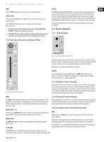
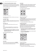
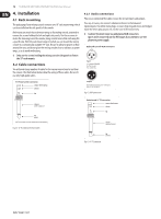
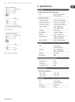
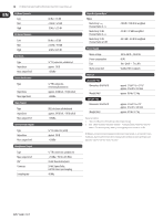
12 EURORACK UB1204FX-PRO/UB1204-PRO User Manual 4. Installation 4.1 Rack mounting The packaging of your mixing console contains two 19" rack mount wings which can be installed on the side panels of the console. Before you can attach the rack mount wings to the mixing console, you need to remove the screws holding the left and right side panels. Use these screws to fasten the two wings onto the console, being careful to note that each wing fits a specific side. With the rack mount wings installed, you can mount the mixing console in a commercially available 19" rack. Be sure to allow for proper air flow around the unit, and do not place the mixing console close to radiators or power amps, so as to avoid overheating. ◊ Only use the screws holding the mixing console side panels to fasten the 19" rack mounts. 4.2 Cable connections You will need a large number of cables for the various connections to and from the console. The illustrations below show the wiring of these cables. Be sure to use only high-grade cables. 4.2.1 Audio connections Please use commercial RCA cables to wire the 2-track inputs and outputs. You can, of course, also connect unbalanced devices to the balanced input/outputs. Use either mono plugs, or ensure that ring and sleeve are bridged inside the stereo plug (or pins 1 & 3 in the case of XLR connectors). ◊ Caution! You must never use unbalanced XLR connectors (pin 1 and 3 connected) on the MIC inputs if you intend to use the phantom power supply. Balanced use with XLR connectors 21 3 input 1 = ground/shield 2 = hot (+ve) 3 = cold (-ve) 12 3 ¼" TS footswitch connector strain relief clamp sleeve tip output For unbalanced use, pin 1 and pin 3 have to be bridged Fig. 4.2: XLR connections sleeve pole 1/ground tip pole 2 The footswitch connects both poles momentarily Fig. 4.1: 1/4" TS connector for foot switch Unbalanced ¼" TS connector strain relief clamp sleeve tip sleeve (ground/shield) tip (signal) Fig. 4.3: 1/4" TS connector
-
 1
1 -
2
-
3
-
4
-
5
-
6
-
 7
7 -
 8
8 -
 9
9 -
 10
10 -
 11
11 -
 12
12 -
 13
13 -
 14
14 -
 15
15 -
 16
16
 |
 |