Behringer EURORACK UB1832FX-PRO Quick Start Guide - Page 9
Controls - mixing console
 |
View all Behringer EURORACK UB1832FX-PRO manuals
Add to My Manuals
Save this manual to your list of manuals |
Page 9 highlights
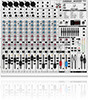
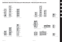
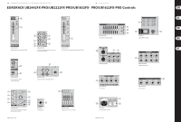
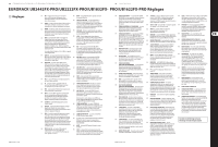
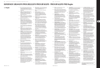
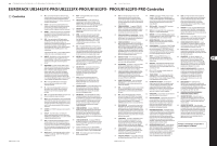
16 EURORACK UB2442FX-PRO/UB2222FX-PRO/UB1832FX-PRO/UB1622FX-PRO 17 Quick Start Guide EURORACK UB2442FX-PRO/UB2222FX-PRO/UB1832FX- PRO/UB1622FX-PRO Controls (EN) Controls (1) MIC - Each mono input channel offers a balanced (17) LINE GAIN - Use this control to adjust the line signal microphone input via XLR as well as switchable phantom levels on channels 13-16 (UB2442FX-PRO only). power (+48 volt) for powering condenser microphones. (18) LEVEL - For level matching, the stereo inputs on the (2) LINE IN - Each mono input also has a balanced line input UB1622FX-PRO, UB1832FX-PRO and UB2222FX-PRO have on a 1/4" jack. You can also connect unbalanced devices a LEVEL switch to select between +4 dBu and -10 dBV. using mono jacks to these inputs. At -10 dBV (homerecording level), the input is more (3) INSERT - Insert points enable the processing of a signal sensitive than at +4 dBu (studio level). with dynamic processors or equalizers. They are sourced (19) BAL - The BAL (ANCE) control has a similar function pre-fader, pre-EQ and pre-aux send. to the PAN control in the mono channels. The balance (4) GAIN - Use the GAIN control to adjust the input gain. This control should always be turned fully counterclockwise whenever you connect or disconnect a signal source to one of the inputs. The scale has 2 different control determines the levels of the left and right input signals relative to each other before both signals are routed to the left/right main mix bus (or odd/even subgroup). value ranges: the first value range (+10 to +60 dB) refers (20) AUX SEND 1, 2 and 4 - The AUX SEND 1 control governs to the MIC input and shows the amplification for the the master send level of the mix created by the individual signals fed in there. channel AUX 1 sends. Likewise, the AUX SEND 2 contol The second value range (+10 to -40 dB) refers to the line input and shows its sensitivity. is the master control for the aux 2 bus, and AUX SEND 4 controls the AUX 4 bus. (5) LOW CUT - Additionally, the mono channels of the mixing consoles have a high-slope LOW CUT filter for eliminating unwanted, low-frequency signal components (75 Hz, 18 dB/octave). (21) AUX SEND 3 (FX) - The FX control determines the signal level for effects processing, i.e. regulates the level to an external (or the internal) effects device. UB1622FX-PRO and UB1832FX-PRO: On these consoles, this function is performed by the AUX SEND 2 control (FX). (6) EQUALIZER - The upper (HIGH) and the lower (LOW) bands are shelving filters that increase or decrease all frequencies above or below their cut-off frequency. The cut-off frequencies of the upper and lower bands (22) SOLO - You can use the SOLO switch to separately monitor the aux sends via the PHONES/CTRL ROOM outputs and check these with the level meters. are 12 kHz and 80 Hz respectively. For the mid range, (23) AUX SEND JACKS - The AUX SEND jack should be used the console features a semi-parametric equalizer when hooking up a monitor power amp or active monitor with a filter quality (Q) of 1 octave, tunable from speaker system. The relevant aux path should be set 100 Hz to 8 kHz. Use the MID control to set the amount pre-fader. of boost or cut, and the FREQ control to determine the central frequency. (24) AUX SEND (FX) - The AUX SEND (FX) jack carries the master aux mix (from the channel's FX controls). (7) PRE - When the PRE switch is pressed down, You can connect this to an external effects device to the associated aux send is taken pre-fader. process the FX bus. The processed signal can then (8) FX - The aux send marked FX offers a direct route to the built-in effects processor and is therefore post-fader and be brought from the effects device back into the STEREO AUX RETURN jacks. post-mute. (25) STEREO AUX RETURN - The STEREO AUX RETURN 1 (9) PAN - The PAN control determines the position of the channel signal within the stereo image. jacks generally serve as the return for the effects mix (created using the post-fader aux sends) by connecting the output of an external effects device. If only the left (10) MUTE - The MUTE switch breaks the signal path pre-channel fader, hence muting that channel in the jack is connected, the AUX RETURN is automatically switched to mono. main mix. The aux sends which are set to post-fader are likewise muted for that channel, while the pre-fader monitor paths remain active irrespective of whether the channel is muted or not. (26) STEREO AUX RETURN FX - The STEREO AUX RETURN FX jacks accept the effects mix return (created using the channel FX sends). (11) MUTE LED - The MUTE LED indicates a muted channel. (27) The first aux send (MON) on this console is used to set up the monitor mix from the channels and route it to the (12) CLIP LED - The CLIP-LED lights up when the input MON SEND fader. signal is driven too high. If this happens, back off the GAIN control and, if necessary, check the setting of the channel EQ. (28) MUTE - Press the MUTE switch to mute the monitor send. (13) SOLO - The SOLO switch is used to route the channel signal to the solo bus (Solo In Place) or to the PFL bus (Pre Fader Listen). This enables you to listen to a channel signal without affecting the main output signal. The signal you hear is taken either before the (29) SOLO - The SOLO switch routes the monitor send to the solo bus (post-fader and post-mute) or to the PFL bus (pre-fader and pre-mute). The position of the MODE switch in the main section determines which of the buses is selected. pan control (PFL, mono) or after the pan and channel (30) STEREO AUX RETURN 1 - The STEREO AUX RETURN 1 fader (Solo, stereo). control determines the level of this signal in the (14) SUB (1-2 and 3-4) - The SUB switch routes the signal to the corresponding subgroups. The UB2442FX-PRO has 4 subgroups (1-2 and 3-4). main mix. If STEREO AUX RETURN 1 is used as effects return, this will determine the level of the effects when mixed with any "dry" channel signal. (15) MAIN - The MAIN switch routes the signal to the main mix bus. (31) STEREO AUX RETURN 1/2 (TO AUX SEND) - The two right-hand STEREO AUX RETURN controls have a special function: they can be used to add an effect to a (16) LOW CUT and MIC GAIN - These two control elements monitor mix. operate on the XLR connectors of the UB2442FX-PRO, and are used to filter out frequencies below 75 Hz (LOW CUT) and to adjust microphone levels (MIC GAIN). (32) STEREO AUX RETURN FX - On consoles UB1622FX-PRO (48) 2-TRACK TO MAIN - When the 2-TRACK TO MAIN (63) SUB OUTPUTS - The subgroup outputs are and UB1832FX-PRO this is the STEREO AUX RETURN 2, switch is depressed, the 2-track input is routed to the unbalanced and provide the mix of those channels on consoles UB2222FX-PRO and UB2442FX-PRO this main mix and thus serves as an additional input for assigned to each subgroup with the SUB switch is the STEREO AUX RETURN 3. Use the STEREO AUX tape machines. You can also connect MIDI instruments (UB2442FX-PRO: switches 1-2 or 3-4) next to the RETURN FX control to determine the level of the signal or other signals here that do not require any channel faders. The EURORACK UB2442FX-PRO already routed from the AUX RETURN FX jacks to the main mix. further processing. has subgroup outputs wired in parallel (1-5, 2-6, etc.). If nothing is connected to these jacks, the output of the built-in effects module will appear. (49) MODE - The MODE switch determines whether the (64) INSERTS - Insert points are very useful to process channels' SOLO switch operates as PFL (Pre Fader Listen) channel signals with dynamic processors or equalizers. (33) MAIN MIX TO SUBS - This switch routes the signal fed or as solo (Solo In Place). Unlike reverb or other effects devices, whose signals are in via the STEREO AUX RETURN FX jacks either to the main mix (not pressed) or to the submix (pressed). (50) MAIN SOLO - The MAIN SOLO LED lights up as soon as a channel or aux send solo switch is pressed. The MODE usually added to the dry signal, dynamic processors are most effective on the complete signal. (34) SOLO RETURNS - Additionally, this model allows you switch must be set to "Solo". (65) DIRECT OUTPUTS - The direct outputs of the to route the aux returns together to the solo bus and the PFL bus. The LED lights up when Solo is on. (35) STEREO AUX RETURN 4 (UB2442FX-PRO only) - This control behaves the same way as the other stereo aux returns. Additionally, it provides for a simple monitor path using the switch PHONES/CTRL ROOM ONLY. (36) PHONES/CTRL ROOM ONLY - Use this switch to route the signal appearing at the AUX RETURN 4 jacks to the control room and headphones outputs. (51) PFL - The PFL LED indicates that the peak meter is set to PFL mode. UB2442FX-PRO (1 each per mono input channel) are ideal for recording if several tracks are to be recorded simultaneously. These unbalanced phone (52) PHONES JACK - You can connect headphones to jacks are post-EQ, post-mute and post-fader. this 1/4" stereo jack (UB2442FX-PRO: 2 phones jacks). (66) FUSE HOLDER/IEC MAINS RECEPTACLE The signal routed to the PHONES connection is the same as that routed to the control room output. (67) POWER SWITCH - Use the POWER switch to turn on (53) LEFT/RIGHT SWITCH - The switches located above the subgroup faders assign the subgroup signal either to the left or right side of the main bus. Similarly, it can the mixing console. The POWER switch should always be in the "Off" position when you are about to connect your unit to the mains. be routed to both sides or none at all. In the latter case, (68) PHANTOM SWITCH - The PHANTOM switch activates (37) MON - The MON switch routes the signals appearing at the submix is present only at the corresponding the phantom power (necessary to operate the AUX RETURN 2 jacks to the monitor path, along with subgroup outputs. condenser microphones) on the XLR sockets of the the monitor signals from the channels. (38) XPQ - The XPQ surround function can be enabled/ disabled with the XPQ TO MAIN switch. This is a built-in effect that widens the stereo width, thus making the sound more lively and transparent. Use the SURROUND control to determine the intensity of this effect. (39) VOICE CANCELLER - Here, you have a filter circuitry (54) EQUALIZER - Use this switch to activate the graphic equalizer. (55) MAIN MIX/MONITOR - This toggles the graphic equalizer between the main mix and the monitor mix. With the switch up (not depressed), the equalizer is active in stereo on the main mix, and inactive on the monitor mix. When the switch is depressed the equalizer is active in mono on the monitor mix, mono channels. The red +48 V LED illuminates when phantom power is on. As a rule, dynamic microphones can still be used with phantom power, provided that they are wired in a balanced configuration. In case of doubt, contact the microphone manufacturer! Check Out behringer.com for Full Manual that lets you almost entirely remove the vocal portion and inactive on the main mix. of a recording. The filter is constructed in such a way that voice frequencies are targeted without majorly affecting the rest of the signal. Additionally, the filter seizes only the middle of the stereo image, exactly there where the vocals are typically located. (56) FEEDBACK DETECTION - The switch turns on the FBQ Feedback Detection System. It uses the LEDs in the frequency band faders to indicate the critical frequencies. On a per-need basis, lower the frequency range in question somewhat in order to avoid feedback. (40) 2-TRACK INPUT - The 2-TRACK INPUT jacks The graphic stereo equalizer has to be turned on in (RCA) are designed to accept a 2-track recorder order to use this function. (e.g. DAT recorder), or they can be used as stereo line input. The output signal of a second EURORACK or the BEHRINGER ULTRALINK PRO MX882 can also be connected here. (57) 24-BIT MULTI-EFFECTS PROCESSOR - Here you can find a list of all presets stored in the multi-effects processor. This built-in effects module produces high-grade standard effects such as reverb, chorus, (41) 2-TRACK OUTPUT - These connectors are wired flanger, delay and various combination effects. Use the in parallel to the MAIN OUT and carry the main mix Aux Send FX on the channels and the Aux Send FX signal (unbalanced). Connect this to the inputs of your master control to determine the input signal of the recording device. The final output level can be adjusted effects processor. via the high-precision MAIN MIX fader. (58) LEVEL - The LED level meter on the effects module (42) LAMP SOCKET - Use this BNC socket to connect a should display a sufficiently high level. Take care to gooseneck lamp (12 V DC, max. 0.5 A). ensure that the clip LED only lights up at peak levels. (43) 2-TRACK - The 2-TRACK switch routes the signal from the 2-TRACK INPUT jacks to the level meter, If it is lit constantly, you are overloading the effects processor and this could cause unpleasant distortion. the CONTROL ROOM OUT outputs and the PHONES (59) PROGRAM - You can select the effect preset by turning jack-this is a simple way to check recorded signals via the PROGRAM control. The display flashes with the monitor speakers or headphones. number of the current preset. To recall the selected (44) SUB 1-2 or SUB - The SUB 1-2 switch routes subgroup 1-2 to the level meter, CONTROL ROOM OUT and phones. preset, press on the button; the flashing stops. You can also recall the selected preset with the foot switch. (45) SUB 3-4 - The SUB 3-4 switch performs a similar function for subgroup 3-4 (UB2442FX-PRO only). (60) MAIN OUTPUTS - The MAIN outputs carry the MAIN MIX signal and are on balanced XLR jacks with a nominal level of +4 dBu. (46) MAIN MIX - The MAIN MIX switch sends the main mix to the CONTROL ROOM OUT and the PHONES output as well as to the level meter. (61) CONTROL ROOM OUTPUTS (CTRL OUT) - The control room output is normally connected to the monitoring system in the control room and carries the stereo mix (47) PHONES/CTRL ROOM - Use this control to adjust the or, when selected, the solo signals. control room output level and the headphones volume. (62) MAIN INS(ERTS) - These are the insert points for the main mix. In the signal path, they are post-main mix amp, but pre-main fader(s).
-
 1
1 -
2
-
3
-
 4
4 -
 5
5 -
 6
6 -
 7
7 -
 8
8 -
 9
9 -
 10
10 -
 11
11 -
 12
12 -
 13
13 -
 14
14 -
15
-
16
-
17
-
18
-
19
-
20
 |
 |