Behringer PRO MIXER DX2000USB Manual - Page 6
Talk Over, Input selection, Gain setting, Equalizer, Output - pro mixer manual
 |
View all Behringer PRO MIXER DX2000USB manuals
Add to My Manuals
Save this manual to your list of manuals |
Page 6 highlights
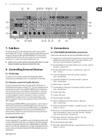
6 PRO MIXER DX2000USB User Manual 3.1 Input selection Inputs are on the DX2000USB's back panel. Your input source is selectable between a pair of stereo inputs by the INPUT switch (1) at the top of the channel strip. An associated pair of LEDs (2) lets you know which input is selected. The choice of inputs depends on which of channels 3 - 7 you are looking at. The mixer is set up as follows: Channel 3 4 5 6 7 Input 1 PHONO/LINE 1 PHONO/LINE 2 PHONO/LINE 3 LINE 1 LINE 2 Tab. 3.1: Stereo channel configuration Input 2 CD 1 / USB CD 2 CD 3 CD 4 CD 5 ◊ Never patch line level devices into your highly sensitive phono inputs. Phono cartridge output is measured in millivolts. Line level signals are of the order of magnitude of a volt. With line levels you are looking at a signal up to 100 times more powerful than the phono pre-amplifier is designed to handle! Press the PHONO/LINE button to allow the PHONO/LINE jacks to operate at line-level. ◊ If for some reason your turntable has a built-in RIAA pre-amp, you should patch it into a line level input. ◊ A mix could include three turntables (channels 3 - 5) and two samplers for creative DJ work, or four CD/cart players plus a stereo tape recorder for a broadcast studio. In fact any line level signal could be patched into any line-level input. 3.2 Gain setting ◊ Gain is dependent on EQ. Set up your EQ before fine-tuning gain. 3.2.1 Quick way Channel input level is continuously monitored by a pair of LEDs (3). CLIP lets you know if you're about to overload the channel (it lights at +18 dB). The SIG. LED only responds to bass frequencies and is perfectly suited to keep an eye on the beats. As long as the signal LED is flashing on the beat (and the CLIP LED isn't) you can be sure the gain is reasonable. Do this for all music channels. Channel gain can be continuously adjusted by the GAIN knob (4) (from -20 to +20 dB). ◊ If you are in the habit of slamming the channel faders all the way up (+6 dB), try to keep your MAIN faders at a compensatory -6 dB to make sure you don't risk distortion. At this level PFL and MAIN meters should show the same level (check this by engaging PFL on the channel currently playing), allowing easy comparison between outgoing (playing) and incoming (cueing) tracks. Keep an eye on the output meters-red spells trouble. Remember-distortion is not volume, and any distortion introduced before the power amplifiers and speakers will worsen your sound and cause amps and speakers to clip sooner. 3.2.2 Gain setting by using PFL Pre-Fader-Listen is the professional way to set gain, and we always recommend you do it if you have the time. Hit the PFL button (13) to temporarily send the channel signal to the PFL meter (39). Adjust GAIN until the PFL meter is hitting the yellow (up to +10 dB) but not the red (clip). Once gain has been set for a channel, release its PFL button. ◊ Normally you will want to PFL only one channel at a time. This might not be true if you are layering tracks, and/or using "Permanent PFL"- see the chapter 7 "HEADPHONES, MONITORS & PFL". Also note that the mono PFL meter is a sum of L and R channel signals. 3.3 Equalizer The channel EQ section comprises three control knobs and two switches. The EQ ON (16) switch activates the tone controls which enable cut and boost of HIGH (6), MID (7) and LOW (8) frequencies respectively (see below for specs.) EQ can sweeten or effect a track, with the fading out and in of frequency bands being very popular. EQ Frequency High Shelving EQ 15 kHz Mid Peaking EQ 1.4 kHz Low Sheiving EQ 50Hz Tab. 3.2: Equalizer of the stereo channels Range +6/-18 dB +6/-25 dB +6/-25 dB Centre OFF OFF OFF ◊ EQ is particularly useful if two or more music tracks are playing together, as frequencies often clash. Low frequencies in particular can phase and cancel, causing uneven bottom-end response. The trick is to cut the bass from all but one track playing. You can roll off the bass by turning LOW fully counterclockwise. 3.4 Output Channel level is controlled by a precision stereo 100-mm fader (14). ◊ The faders used are high-quality true-log faders. These give ultrasmooth operation even at low levels, on a par with those used in the most expensive studio consoles. Press the CROSSFADER switch (17) to send the channel signal to either of the two stereo submixes, which we call X and Y. The ASSIGN button (18) selects between these two submixes, and a pair of LEDs (19) clearly show you which of X or Y is currently selected per channel. The X and Y mixes are then routed to opposite ends of the main crossfader (33). ◊ You can immediately tell if any channel is switched on (CROSSFADER switch depressed) by looking at the master ASSIGN X and ASSIGN Y (36) indicators situated under the crossfader. 4. Talk Over Let's say you are talking over a music intro. You would almost certainly want to attenuate the music while you speak. The DX2000USB talk over system does this for you-automatically. Depressing the TALK OVER button (11) on a mic channel engages the talk over system. You can leave this button down all the time- it will not affect the music unless you speak into the mic, provided you set the system up correctly. How do you do this? If you look to the left of the main bargraph meters you will see three rotary controls and two LEDs. These are the master talk over adjustments you will want to make. Once you have set them up for your system you will probably not have to alter them unless something else is changed. SENSITIVITY (23) sets the speech level threshold at which attenuation (also called gain reduction) kicks in once talk over is activated by a mic channel signal. TIME (24) controls the rate at which music volume recovers after a mic channel signal has activated the automatic music level reduction process. DAMPING (25) allows you to adjust the depth of music attenuation triggered by the mic channel signal.
-
 1
1 -
 2
2 -
 3
3 -
 4
4 -
 5
5 -
 6
6 -
 7
7 -
 8
8 -
 9
9 -
 10
10 -
 11
11 -
 12
12 -
13
-
14
-
15
-
16
 |
 |
