Behringer TUBE ULTRAGAIN MIC200 Quick Start Guide - Page 21
Controls - mic preamp
 |
View all Behringer TUBE ULTRAGAIN MIC200 manuals
Add to My Manuals
Save this manual to your list of manuals |
Page 21 highlights
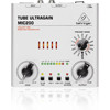
40 TUBE ULTRAGAIN MIC200 TUBE ULTRAGAIN MIC200 Controls (EN) Controls (1) The GAIN control allows you to (5) This +48 V switch activates the control the gain from +26 to +60 dB phantom power supply for the XLR to the input signal. This control should input. Phantom power supply is be set all the way to the left when required for operating condenser (dis)connecting a sound source from microphones. Dynamic microphones the MIC200. When all connections require no phantom power. are made, slowly start raising the gain control. (6) Press the LOW CUT switch to eliminate undesired subsonic noise, (2) We recommend using the LED such as floor rumble. meter to adjust gain. The LED chain displays the output signal level in dB. (7) Please make sure that the clip LED never lights up permanently. It should light up only at peak signals, but it should never be on all the time. With the PHASE REVERSE switch, the input signal is reversed by 180°. This function is available for both mic and line signals. Use this function in a multi-microphone setup if you detect phase cancellations in specific (3) If your MIC200 is connected to the frequency bands. mains via the enclosed power supply unit, the POWER LED lights up to (8) indicate that your MIC200 is running. The OUTPUT control governs the output level within a range from -∞ to +10 dB. If the control is (4) The 20 dB PAD switch reduces turned all the way to the left, there the input sensitivity by 20 dB is no output signal at all. The more (switch pressed). The appropriate the control is turned to the right, setting depends on the equipment the higher the output level. connected. Generally speaking, lowering the signal level in mic (9) The PREAMP MODE rotary switch applications is not recommended. gives you a wide selection of No matter what your application is, preamp presets. The options available the clip LED warns you to reduce the are: WARM, WARM/LIMITER, gain setting to avoid distortion. LIMITER and NEUTRAL. 41 Quick Start Guide (10) The balanced ¼" TRS INPUT of your MIC200 can be used to connect your electric guitar, for example. This input is wired parallell to the XLR input. Ideally, the balanced XLR INPUT should be used to connect a microphone. ◊ In contrast to its outputs, the MIC200's inputs should never be used simultaneously! (11) This is the balanced XLR OUTPUT of your MIC200. Use this connector to feed the XLR input of your mixing console, multitrack recorder or power amp. The balanced ¼" TRS OUTPUT of your MIC200 can also be connected to a mixer, recording system or power amp. (12) Use the POWER SUPPLY CONNECTOR to hook up the enclosed power supply unit. Next to this connector you'll find the strain relief clamp, which prevents accidental release of the power supply. Check Out behringer.com for Full Manual
-
 1
1 -
2
-
3
-
4
-
5
-
6
-
7
-
8
-
9
-
10
-
11
-
12
-
13
-
14
-
15
-
 16
16 -
 17
17 -
 18
18 -
 19
19 -
 20
20 -
 21
21 -
 22
22 -
 23
23 -
 24
24 -
 25
25 -
 26
26 -
27
-
28
-
29
-
30
-
31
-
32
-
33
 |
 |
