Behringer UB1204FX-PRO User Manual - Page 6
Control Elements And Connectors - eurorack effects
 |
View all Behringer UB1204FX-PRO manuals
Add to My Manuals
Save this manual to your list of manuals |
Page 6 highlights
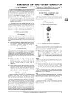
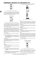
EURORACK UB1204-PRO/UB1204FX-PRO 2.1.4 Routing switch, solo and channel fader Fig. 2.2: The equalizer of the input channels The upper (HI) and the lower band (LO) are shelving filters that increase or decrease all frequencies above or below their cut-off frequency. The cut-off frequencies of the upper and lower band are 12 kHz and 80 Hz respectively. The mid band is configured as a peak filter with a center frequency of 2.5 kHz. 2.1.3 Aux sends Fig. 2.3: The AUX SEND controls in the channel strips Aux sends take signals via a control from one or more channels and sum these signals to a so-called bus. This bus signal is sent to an aux send connector and then routed, for example, to an active monitor speaker or an external effects device. The return from an external effect can then be brought back into the console via the aux return connectors. For situations which require effects processing, the aux sends are usually switched post-fader so that the effects volume in a channel corresponds to the position of the channel fader. If this were not the case, the effects signal of the channel would remain audible even when the fader is turned to zero. When setting up a monitor mix, the aux sends are generally switched to pre-fader; i.e. they operate independently of the position of the channel fader. Both aux sends are mono, are sourced after the equalizer and offer up to +15 dB gain. + If you press the MUTE/ALT 3-4 switch, aux send 1 is muted, provided that it is switched postfader. However, this does not affect the aux send 2 of the UB1204FX-PRO. AUX 1 (MON) In the UB1204FX-PRO, aux send 1 can be switched pre-fader and is thus particularly suitable for setting up monitor mixes. In the UB1204-PRO, the first aux send is labeled MON and is permanently switched pre-fader. PRE When the PRE switch is pressed, aux send 1 is sourced pre- fader. AUX 2 (FX) The aux send labeled FX is for sending to effects devices and is thus set up to be post-fader. In the UB1204FX-PRO, the FX send is routed directly to the built-in effects processor. + If you wish to use the internal effects processor, the STEREO AUX RETURN 2 connectors should not be in use. + UB1204FX-PRO: you can also connect an external effects processor to aux send 2, however the internal effects module will be muted. Fig. 2.4: Panorama and routing controls PAN The PAN control determines the position of the channel signal within the stereo image. This control features a constant-power characteristic, which means the signal is always maintained at a constant level, irrespective of position in the stereo panorama. MUTE/ALT 3-4 You can use the MUTE/ALT 3-4 switch to divert the channel from the main mix bus to the Alt 3-4 bus. This mutes the channel from the main mix. MUTE LED The MUTE LED indicates that the relevant channel is diverted to the submix (Alt 3-4 bus). PEAK LED The PEAK LED lights up when the input signal is driven too high. In this case, turn down the GAIN control and, if necessary, check the setting of the channel EQ. SOLO The SOLO switch (UB1204FX-PRO only) is used to route the channel signal to the solo bus (Solo In Place) or to the PFL bus (Pre Fader Listen). This enables you to monitor a channel signal without affecting the main output signal. The signal you hear is sourced either before (PFL, mono) or after (solo, stereo) both the pan control and the channel fader (see chapter 2.3.6 “Level meters and monitoring”). The channel fader determines the level of the channel signal in the main mix (or submix). 2.2 Stereo channels 2.2.1 Channel inputs Fig. 2.5: Stereo channel inputs and LEVEL switch Each stereo channel has two balanced line level inputs on 1/4" connectors for left and right channels. If only the connector marked “L” is used, the channel operates in mono. Stereo channels are designed to handle typical line level signals. Both inputs can also be used with unbalanced jacks. 6 2. CONTROL ELEMENTS AND CONNECTORS
-
 1
1 -
 2
2 -
 3
3 -
 4
4 -
 5
5 -
 6
6 -
 7
7 -
 8
8 -
 9
9 -
 10
10 -
 11
11 -
 12
12 -
13
 |
 |
