Behringer ULTRABASS BXL3000A Manual - Page 5
Control Elements, And Connections - ultrabass
 |
View all Behringer ULTRABASS BXL3000A manuals
Add to My Manuals
Save this manual to your list of manuals |
Page 5 highlights
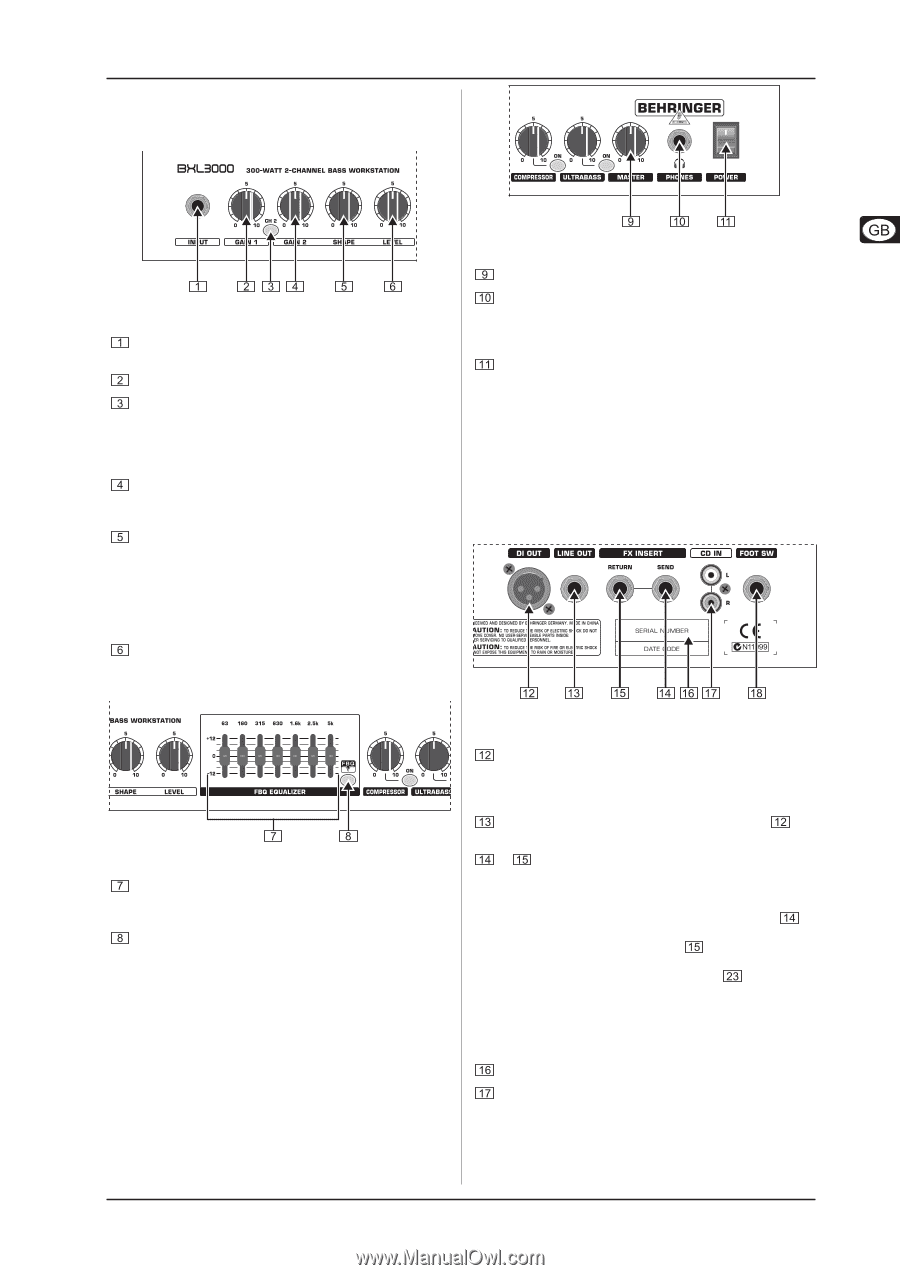
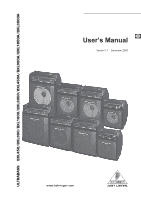
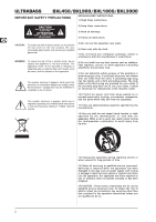
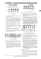
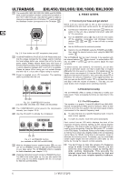
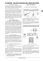
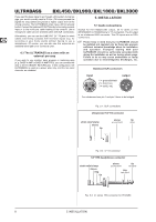
ULTRABASS BXL450A/BXL900A/BXL1800A/BXL3000A 2. CONTROL ELEMENTS AND CONNECTIONS Fig. 2.1: The input section INPUT. Connect your bass guitar to this input jack on the ULTRABASS (¼" TS jack). The GAIN 1 control determines the input gain on channel 1. Use the CH 2 button to switch over between the two channels. The CH 2 button lights up when channel 2 has been activated. On the models BXL1800, BXL3000, BXL1800A and BXL3000A, the channels can also be selected using the foot switch shipped with the unit. The GAIN 2 control sets the degree of distortion of channel 2. The further the control is turned clockwise, the higher the degree of distortion. SHAPE is a special filter for your personal sound design. It gives you numerous options for shaping your bass sound. Application examples of the shape function can be found in chapter 3.2.2. + The Shape filter is only effective on channel 2. The signal in channel 1 remains unprocessed. Use the LEVEL control to adjust the volume of channel 2. Use this control to achieve the balance in volume that you want between channels 1 and 2. Fig. 2.3: The master section Use the MASTER control to set the overall volume. The PHONES jack (¼" TRS jack) is for connecting a pair of headphones. You can use headphones from the BEHRINGER HP Series. This connector, when in use, mutes the built-in bass speaker. The POWER switch powers up your ULTRABASS. The POWER switch should always be in the “Off” position before you connect the ULTRABASS to the main power source. + Please note: The POWER switch does not fully disconnect the unit from the mains power cord plug or extention cord. To disconnect the unit from the main power source, pull out the main cord plug or appliance coupler. When installing the product, ensure the plug or appliance coupler is readily operable. Unplug the power cord when the unit is not used for prolonged periods of time. Fig. 2.2: The FBQ EQUALIZER The FBQ EQUALIZER has 7 slide controls (BXL450 and BXL450A: 5 slide controls), one for each frequency band. The maximum boost/cut is 12 dB. The FBQ switch activates the FBQ spectrum analyzer. The control LEDs, which are identical in brightness when FBQ is off, now show the energy content of each frequency band by lighting up with varying degrees of brightness. The equalizer function is always active, irrespective of the FBQ function. (For details on the FBQ function see chapter 3.2.1.) Fig. 2.4: The rear-panel connectors (BXL1800, BXL3000, BXL1800A and BXL3000A) Use the balanced DI OUT(PUT) (XLR) to route the audio signal from the ULTRABASS to the input on a mixing console. The signal is taken from the point between the equalizer and the MASTER control. As an alternative to taking the signal from output LINE OUT signal (¼" TS jack) can also be used. , the + FX INSERT (not available on BXL450 and BXL900 or on BXL450A and BXL900A): The ULTRABASS features a serial insert path, which allows you to connect external effects devices (e. g. wah-wah pedal, floor effects or 19" effects processors). Connect the SEND jack to the input on the effects device. Connect the output on the effects device to the RETURN jack on the ULTRABASS. In the signal path of the amplifier, the FX insertion point occurs before the Ultrabass processor ( ). + The INSERT SEND can also be used as a parallel output, for example, to connect a tuner. As long as the RETURN jack is not in use, there will be no break in the internal signal path. SERIAL NUMBER. The CD IN input (RCA) allows you to connect an external stereo signal. For instance, you can play along with your favorite songs played back from CD or MD, or with a drum computer. + The models BXL450, BXL900, BXL450A and BXL900A have the CD IN connector installed on the front panel. 2. CONTROL ELEMENTS AND CONNECTIONS 5
-
 1
1 -
 2
2 -
 3
3 -
 4
4 -
 5
5 -
 6
6 -
 7
7 -
 8
8 -
 9
9 -
 10
10
 |
 |