Behringer ULTRAGAIN PRO-8 DIGITAL ADA8000 Quick Start Guide - Page 8
Controls, Controles
 |
View all Behringer ULTRAGAIN PRO-8 DIGITAL ADA8000 manuals
Add to My Manuals
Save this manual to your list of manuals |
Page 8 highlights
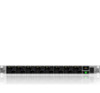
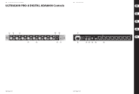
14 ULTRAGAIN PRO-8 DIGITAL ADA8000 ULTRAGAIN PRO-8 DIGITAL ADA8000 Controls (EN) Controls (1) The SIG LED lights up when a signal is present (11) Power is supplied via an IEC connector. at one of the inputs. The matching cable is provided with the unit. (2) If the input level is too high, the CLIP LED (12) All analog input signals are converted into the lights up. The CLIP LED should light up only standard ADAT format and can be taken at the with signal peaks but never all the time. 8-CHANNEL DIGITAL OUT. This output can (3) Use the GAIN control to set the input gain. The gain ranges from +10 to +60 dB. The GAIN control governs both the LINE IN and the MIC IN input. be used to feed an ADAT recorder or any other device featuring an ADAT input. Please note that a signal present at the Digital In will not be routed to the Digital Out. (4) This is the balanced ¼" TRS LINE IN connector. A connected analog LINE IN or MIC IN signal is not routed to the analog LINE OUT connector (16). Instead, it will reach the (13) At the 8-CHANNEL DIGITAL IN, you can connect an ADAT device. The signal will automatically be routed to the 8 analog LINE OUT connectors. ADAT OUT interface. (14) Use the WC IN connector to connect devices (5) This is the balanced MIC IN XLR connector. For example, you can connect your microphone here. Permanently fixed functions are assigned to this key section: for the exter-nal synchronization of your ADA8000. This BNC connector is only active, when the respective setting on the rear is made (see (15)). When, for example, various devices are interconnected in a digital (6) As long as the ADA8000 functions as master, recording system with, say, a digital mixing sending a clock signal, the SYNC MASTER LED console, all digital units connected have to be lights up. The appropriate setting can be made synchronized via a shared wordclock signal. on the rear (see (15)). (15) The setting of this switch depends on the (7) When the ADA8000 is synchronized externally application of your ADA8000. If an external (either ADAT or wordclock IN), the SYNC ADAT recorder is supposed to send the LOCKED-LED lights up. wordclock signal (in this case, the ADA8000 (8) Press the +48 V switch to provide condenser microphones which are connected to the MIC IN inputs with the required phantom power. Dynamic microphones do not require this external power supply. When the switch is depressed, phantom power is active on all inputs. functions as SLAVE), the switch has to be set to the ADAT IN position. Please also note the instructions given in the user's manual of your ADAT device. When your ADA8000 functions as Master (here, the ADA8000 sends the wordclock signal) please use the switch to select the sampling rate of your choice (either 44,1 or 48 kHz). (9) The POWER switch powers the ADA8000 on. You should always make sure that the POWER switch is in the "Off" position when initially connecting the unit to the mains. (16) Your ADA8000 features eight LINE OUTs on balanced XLR connectors. An input signal present at the ADAT IN will automatically be transferred into eight independent (10) FUSE COMPARTMENT / VOLTAGE signals and routed to the eight analog SELECTION. Before connecting the unit to LINE OUT connectors. a power outlet, please make sure that the selected voltage matches your local voltage. When replacing fuses, please make sure Check Out behringer.com for Full Manual that you always use fuses of the same type. Some units allow for switching between 230 V und 120 V. Please note: when connecting a unit intended for the European market to a 120 V power outlet, you must also replace the factory fuse with a higher-value fuse. 15 Quick Start Guide (ES) Controles (1) El LED SIG se encenderá cuando haya un señal (11) La alimentación se suministra a través de un en una de las entradas. conector IEC. El cable es suministrado junto (2) Si el nivel de salida es muy alto, se encenderá con la unidad. el LED CLIP. Este LED debería encenderse sólo (12) Todas las señales de entrada analógicas con picos de señal, pero nunca todo el tiempo. son convertidas al formato estándar ADAT y (3) Use el control GAIN para establecer la ganancia de entrada. El rango de ganancia es de +10 a +60 dB. El control GAIN gobierna las entradas de LINE IN y de MIC IN. pueden tomarse de la salida OUT 8-CHANNEL DIGITAL. Esta salida puede usarse para alimentar el grabador ADAT u otro dispositivo que use una salida ADAT. Tome nota de que una señal presente en DIGITAL IN no será (4) Este es el conector LINE IN TRS de ¼" llevada a DIGITAL OUT. balanceado. Una señal analógica LINE IN o MIC IN conectada no se dirige al conector analógico LINE OUT (16). En cambio, llegará al interface ADAT OUT. (13) Puede conectar un dispositivo ADAT en la entrada IN 8-CHANNEL DIGITAL. La señal será automáticamente conducida a los 8 conectores analógicos LINE OUT. (5) Este es el conector MIC IN XLR balanceado. Aquí puede, por ejemplo, conectar su micrófono. (14) Use el conector WC IN para conectar dispositivos para la sincronización externa de su ADA8000. Este conector BNC estará (6) Si el ADA8000 funciona como maestro, únicamente activo cuando haga los ajustes enviando una señal de reloj, el LED SYNC necesarios en la parte posterior (ver (15)). MASTER se encenderá. Puede ajustarse Por ejemplo, cuando varios dispositivos correctamente en la parte trasera (ver (15)). estén interconectados en un sistema de (7) Cuando el ADA8000 esté sincronizado externamente (con ADAT o bien wordclock IN), se encenderá el LED SYNC LOCKED. grabación digital con, digamos, una mesa de mezclas digital, todas las unidades digitales conectadas tienen que estar sincronizadas a través de un señal de wordclock compartida. (8) Pulse el conmutador +48 V para proporcionar a los micrófonos de condensador, que están conectados en MIC IN, la alimentación fantasma necesaria. Los micrófonos dinámicos no necesitan esta fuente de alimentacion externa. Cuando el conmutador está pulsado, la alimentación fantasma está activa en todas las entradas. (15) Los ajustes de este conmutador dependerán de la aplicación que le quiera dar a su ADA8000. Si suponemos que un grabador externo ADAT debe enviar una señal de wordclock (en este caso, el ADA8000 funciona como esclavo (SLAVE), el conmutador tiene que estar ajustado en posición ADAT IN. Compruebe las instrucciones que se presentan (9) El conmutador POWER conecta el ADA8000. en el manual de usuario de su dispositivo Asegúrese siempre de que el conmutador ADAT. Cuando su ADA8000 funciona como POWER está en posición "OFF" cuando enchufe maestro (MASTER) (en este caso, el ADA8000 esta unidad. envía la señal de wordclock), utilice el (10) COMPARTIMIENTO DE FUSIBLES / SELECCIÓN DE VOLTAJE. Antes de conectar conmutador para seleccionar el rango de su elección (ó 44,1 ó 48 kHz). la unidad a la toma de corriente, por favor (16) Su ADA8000 dispone de ocho LINE OUTs asegúrese de que el voltaje seleccionado en conectores XLR balanceados. Una señal se corresponde con el voltaje local. Cuando de entrada presente en ADAT IN será sustituya los fusibles, asegúrese de que utiliza automáticamente transferida a ocho señales fusibles del mismo tipo. Algunas unidades independientes y llevada a los conectores permiten alternar entre 230 V y 120 V. analógicos LINE OUT. Atención: cuando conecte una unidad destinada a un mercado europeo a una toma Si quiere acceder al manual de instrucciones de corriente de 120 V, debe sustituir el fusible completo, vaya a la página web behringer.com suministrado de fábrica por uno de valor más alto.
-
 1
1 -
2
-
 3
3 -
 4
4 -
 5
5 -
 6
6 -
 7
7 -
 8
8 -
 9
9 -
 10
10 -
 11
11 -
 12
12 -
 13
13 -
14
-
15
 |
 |
