Biostar 945GC-M7TE Setup Manual
Biostar 945GC-M7TE Manual
 |
View all Biostar 945GC-M7TE manuals
Add to My Manuals
Save this manual to your list of manuals |
Biostar 945GC-M7TE manual content summary:
- Biostar 945GC-M7TE | Setup Manual - Page 1
945GC-M7 TE Setup Manual FCC Information and Copyright This equipment has been tested and found to radiate radio frequency energy and, if not installed and used in accordance with the instructions, may cause harmful interference to radio communications. There is no guarantee that interference will - Biostar 945GC-M7TE | Setup Manual - Page 2
Motherboard Features 2 1.4 Rear Panel Connectors 3 1.5 Motherboard Layout 4 Chapter 2: Hardware Installation 5 2.1 Installing Central Processing Unit (CPU 19 4.1 Driver Installation Note 19 4.2 Award BIOS Beep Code 20 4.3 Extra Information 20 4.4 Troubleshooting 21 Chapter - Biostar 945GC-M7TE | Setup Manual - Page 3
945GC-M7 TE 1.1 BEFORE YOU START Thank you for choosing our product. Before you start installing the motherboard, please make sure you follow the instructions Rear I/O Panel for ATX Case X 1 Installation Guide X 1 Fully Setup Driver CD X 1 (full version manual files inside) Serial ATA Cable X 1 FDD - Biostar 945GC-M7TE | Setup Manual - Page 4
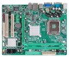
Motherboard Manual 1.3 MOTHERBOARD FEATURES SPEC LGA 775 Supports Hyper-Threading Intel Core2Duo / Pentium 4 / Pentium D / Execute Disable Bit CPU Celeron D / Celeron 4xx processor up to 3.8 Enhanced Intel " function DIMM Slots x 2 Main Memory Each DIMM supports 256/512MB & 1GB DDR2 Max - Biostar 945GC-M7TE | Setup Manual - Page 5
Port VGA port LAN port USB Port Audio Jack Board Size 190 (W) x 239 (L) mm OS Support Windows XP / VISTA 945GC-M7 TE SPEC x1 Supports front panel facilities x1 Supports front panel audio function x1 Supports CD audio-in function x1 Supports digital audio out function x1 CPU Fan - Biostar 945GC-M7TE | Setup Manual - Page 6
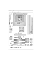
Motherboard Manual 1.5 MOTHERBOARD LAYOUT JKBMS1 LGA775 COJMC1OM1 CPU1 JATXPWR2 JCFAN1 JATXPWR1 JVGA1 DDR2_A1 DDR2_B1 IDE1 JUSB2 JUSBV1 JRJ45USB1 JAUDIO1 Intel 945GC DVIJ1(Optional) PEX16_1 JSFAN1 LAN JCDIN1 Codec JAUDIOF1 PEX1_1 BAT1 BIOS JCMOS1 PCI1 JSPDIF_OUT1 PCI2 JPRNT1 - Biostar 945GC-M7TE | Setup Manual - Page 7
945GC-M7 TE CHAPTER 2: HARDWARE INSTALLATION 2.1 INSTALLING CENTRAL PROCESSING UNIT (CPU) Special Notice: Remove Pin Cap before installation, and make good preservation for future use. When the CPU is removed, cover the Pin Cap on the empty socket to ensure pin legs won't be damaged. Pin-Cap Step 1: - Biostar 945GC-M7TE | Setup Manual - Page 8
Motherboard Manual Step 2: Look for the triangular cut edge on socket, and the golden dot on CPU should point forwards this triangular cut edge. The CPU will fit only in the correct orientation. Step 2-1: Step 2-2: Step 3: Hold the CPU down firmly, and then lower the lever to locked position to - Biostar 945GC-M7TE | Setup Manual - Page 9
945GC-M7 TE 2.2 FAN HEADERS These fan headers support cooling-fans built in the computer. The fan cable and connector may be different according to the fan manufacturer. Connect the fan cable to the connector while matching the black wire to pin#1. JCFAN1: CPU Fan Header 1 4 Pin Assignment 1 Ground - Biostar 945GC-M7TE | Setup Manual - Page 10
DDR2_A1 DDR2_B1 Motherboard Manual 2.3 INSTALLING SYSTEM MEMORY A. DDR2 Module 1. Unlock a DIMM slot by pressing the retaining clips outward. Align a DIMM on the slot such that the notch on the - Biostar 945GC-M7TE | Setup Manual - Page 11
945GC-M7 TE Total Memory Size Max memory 2GB. C. Dual Channel Memory Installation To trigger the Dual Channel function of the motherboard same (x8 or x16) D. FSB Supporting Table According to the FSB frequency of the installed CPU, the motherboard could support DDR2 400/533/667 modules. Please - Biostar 945GC-M7TE | Setup Manual - Page 12
Motherboard Manual 2.4 CONNECTORS AND SLOTS FDD1: Floppy Disk Connector The motherboard provides a standard floppy disk connector that supports 360K, 720K, 1.2M, 1.44M and 2.88M floppy disk types. This connector supports the provided floppy drive ribbon cables. 33 1 34 2 IDE1: Hard Disk - Biostar 945GC-M7TE | Setup Manual - Page 13
945GC-M7 TE PEX16_1: PCI-Express x16 Slot - PCI-Express 1.0a compliant. - Maximum PCI-Express supports a raw bit-rate of 2.5Gb/s on the data pins. - 2X bandwidth over the traditional PCI architecture. PEX16_1 PEX1_1 PCI1~PCI2: Peripheral Component Interconnect Slots The motherboard is equipped - Biostar 945GC-M7TE | Setup Manual - Page 14
Motherboard Manual CHAPTER 3: HEADERS & JUMPERS SETUP 3.1 HOW TO SETUP JUMPERS The illustration shows how to set up jumpers. When the jumper cap is placed on pins, the - Biostar 945GC-M7TE | Setup Manual - Page 15
945GC-M7 TE JATXPWR1: ATX Power Source Connector This connector allows user to connect 24-pin power connector on the ATX : ATX Power Source Connector By connecting this connector, it will provide +12V to CPU power circuit. 4 3 1 2 Pin Assignment 1 +12V 2 +12V 3 Ground 4 Ground 13 - Biostar 945GC-M7TE | Setup Manual - Page 16
Motherboard Manual JUSB3/JUSB4: Headers for USB 2.0 Ports at Front Panel This motherboard provides 2 10 NC SATA1~SATA4: Serial ATA Connectors The motherboard has a PCI to SATA Controller with 4 channels SATA interface, it satisfies the SATA 2.0 spec and with transfer rate of 3Gb/s. SATA4 SATA3 - Biostar 945GC-M7TE | Setup Manual - Page 17
945GC-M7 TE JSPDIF_OUT1: Digital Audio out Connectors This connector allows user to connect the PCI bracket SPDIF output header. Pin Assignment 1 +5V 2 SPDIF_OUT1 3 Ground 3 1 JAUDIOF1: Front Panel - Biostar 945GC-M7TE | Setup Manual - Page 18
Motherboard Manual JCDIN1: CD-ROM Audio-in Connector This connector allows user the jumper on pin2-3, it allows user to restore the BIOS safe setting and the CMOS data, please carefully follow the procedures to avoid damaging the motherboard. 13 Pin 1-2 Close: Normal Operation (Default). 13 13 - Biostar 945GC-M7TE | Setup Manual - Page 19
945GC-M7 TE DVIJ1: Connector for DVI Daughter Card Adapter (Optional) This connector is voltage. JUSBV1 3 1 3 1 Pin 1-2 close JUSBV2 31 3 1 Pin 2-3 close Note: In order to support this function "Power-On system via USB device," "JUSBV1/ JUSBV2" jumper cap should be placed on Pin 2-3 individually - Biostar 945GC-M7TE | Setup Manual - Page 20
Motherboard Manual JPRNT1: Printer Port Connector This header allows you to connector printer on the PC. Pin Assignment 1 -Strobe 2 -ALF 3 Data 0 4 -Error 5 Data 1 6 -Init 7 Data 2 8 -Scltin 9 Data 3 - Biostar 945GC-M7TE | Setup Manual - Page 21
HELP 945GC-M7 TE 4.1 DRIVER INSTALLATION NOTE After you installed your operating system, please insert the Fully Setup Driver CD into your optical drive and install the driver for better system performance. You will see the following window after you insert the CD The setup guide will auto - Biostar 945GC-M7TE | Setup Manual - Page 22
Motherboard Manual 4.2 AWARD BIOS BEEP CODE Beep Sound Meaning One long beep followed by two short Video card not found or video card beeps memory bad High-low siren sound CPU overheated System will shut down automatically One Short beep when system boot-up No error found during POST Long - Biostar 945GC-M7TE | Setup Manual - Page 23
945GC-M7 TE 4.4 TROUBLESHOOTING Probable Solution 1. No power to the system at all 1. Make sure power cable is Power light don't illuminate, fan securely plugged in. inside power supply does not turn 2. Replace cable. on. 3. Contact technical support CMOS Failure." Review system's equipment - Biostar 945GC-M7TE | Setup Manual - Page 24
information. Also, in the About panel, you can get detail descriptions about BIOS model and chipsets. In addition, the frequency status of CPU, memory, VGA and PCI along with the CPU speed are synchronically shown on our main panel. Moreover, to protect users' computer systems if the setting is not - Biostar 945GC-M7TE | Setup Manual - Page 25
945GC-M7 TE 5.3 INSTALLATION 1. Execute the setup execution file, and then the following dialog will pop up. Please click "Next" Click "Finish" button. Usage: The following figures are only for reference, the screen printed in this user manual will change according to your motherboard on hand. 23 - Biostar 945GC-M7TE | Setup Manual - Page 26
; the utility's first window you will see is Main Panel. Main Panel contains features as follows: a. Display the CPU Speed, CPU external clock, Memory clock, VGA clock, and PCI clock information. b. Contains About, Voltage/Overclock, and Hardware Monitor Buttons for invoking respective panels. The - Biostar 945GC-M7TE | Setup Manual - Page 27
945GC-M7 TE 3. Overclock/Overvoltage Panel Click the Overclock/Overvoltage button in the Main Panel, the button will be highlighted and the Overclock/Overvoltage Panel will show up as the following figure. As you can see, the Overclock Panel is on the right side, and the Overvoltage Panel is on the - Biostar 945GC-M7TE | Setup Manual - Page 28
Motherboard Manual Overclock Panel contains these features: a. "Auto-Overclock": User can click this button and [ verified best and stable frequency. b. "Verify": If you use the "Manual Adjust" bar to adjust the CPU frequency, then you can click this button and [WarpSpeeder™ III] will proceed - Biostar 945GC-M7TE | Setup Manual - Page 29
945GC-M7 TE Overvoltage Panel contains these features: a. "CPU Voltage": This function allows user to adjust CPU voltage. Click on "+" to increase or "-" to decrease the CPU voltage. b. "Memory Voltage": This function allows user to adjust Memory voltage. Click on "+" to increase or "-" to decrease - Biostar 945GC-M7TE | Setup Manual - Page 30
Motherboard Manual 5. About Panel Click the "about" button in Main Panel, the button will be highlighted and the About Panel will show up as the following figure. In this panel, you can get model name and detail information in hints of all the chipset that are related to overclocking. You can also - Biostar 945GC-M7TE | Setup Manual - Page 31
945GC-M7 TE This page is intentionally left blank. 29 - Biostar 945GC-M7TE | Setup Manual - Page 32
Motherboard Manual APPENDENCIES: SPEC IN OTHER LANGUAGE GERMAN Spezifikationen LGA 775 Intel Core2Duo / Pentium 4 / Pentium D / Unterstützt Hyper-Threading Celeron D / Celeron 4xx Prozessoren mit bis zu Execute Disable Bit CPU 3,8 GHz Enhanced Intel Version 2.0 LAN Atheros L2 10 - Biostar 945GC-M7TE | Setup Manual - Page 33
VGA-Anschluss /A LAN-Anschluss USB-Anschluss Audioanschluss Platinengröße 190 mm (B) X 239 mm (L) OS-Unterstüt Windows XP / VISTA zung 945GC-M7 TE tzt die digitale Audioausgabefunktion CPU-Lüfterstromversorgungsanschluss (mit x1 x1 x1 x1 x1 x4 x3 Biostar behält sich das Recht vor, ohne Ankündigung - Biostar 945GC-M7TE | Setup Manual - Page 34
Motherboard Manual FRANCE SPEC LGA 775 Prend en charge les technologies Processeurs Intel Core2Duo / Pentium 4 / Hyper-Threading Pentium D / Celeron D / Celeron 4xx jusqu'à 3,8 UC d'exécution de bit de désactivation GHz Intel SpeedStep® optimisée *It is recommended to use processors with - Biostar 945GC-M7TE | Setup Manual - Page 35
PS/2 x1 Souris PS/2 x1 E/S du Port série x1 panneau Port VGA x1 arrière Port LAN x1 Port USB x4 Fiche audio x3 Dimensions 190mm (l) X 239 mm (H) de la carte Support SE Windows XP / VISTA 945GC-M7 TE Chaque connector prend en charge 1 Port d'imprimante Chaque connecteur prend en - Biostar 945GC-M7TE | Setup Manual - Page 36
Motherboard Manual ITALIAN SPECIFICA LGA 775 Processore Intel Core2Duo / Pentium 4 / Supporto di Hyper-Threading CPU Pentium D / Celeron D / Celeron 4xx fino a Execute Disable Bit 3.8 GHz Enhanced Intel Compatibile specifiche SATA Versione 2.0. LAN Atheros L2 Negoziazione automatica 10 - Biostar 945GC-M7TE | Setup Manual - Page 37
945GC-M7 TE SPECIFICA Connettore floppy la funzione d'output audio digitale Alimentazione ventolina CPU (con funzione x1 Smart Fan) Collettore ventolina VGA x1 posteriore Porta LAN x1 Porta USB x4 Connettore audio x3 Dimension 190 mm (larghezza) x 239 mm (altezza) i scheda Sistemi Biostar - Biostar 945GC-M7TE | Setup Manual - Page 38
Motherboard Manual SPANISH Especificación LGA 775 Procesador Intel Core2Duo / Pentium 4 / Admite Hyper-Threading Pentium D / Celeron D / Celeron 4xx hasta Bit de deshabilitación de ejecución CPU 3,8 GHz Intel SpeedStep® Mejorado *It is recommended to use processors with Tecnología Extended - Biostar 945GC-M7TE | Setup Manual - Page 39
945GC-M7 TE Especificación Conector disco flexible X1 Cada conector soporta 2 unidades de disco flexible Conector IDE X1 Cada conector soporta 2 dispositivos IDE Conector Puerto de impresora X1 Cada conector soporta 1 Puerto de impresora Conector SATA X4 Cada conector soporta 1 - Biostar 945GC-M7TE | Setup Manual - Page 40
Motherboard Manual PORTUGUESE ESPECIFICAÇÕES LGA 775 Suporta as tecnologias Hyper-Threading Processador Intel Core2Duo / Pentium 4 / Execute Disable Bit CPU PentiumD / Celeron D / Celeron 4xx até 3,8 GHz Enhanced Intel SpeedStep® *It is recommended to use processors with 95W Extended - Biostar 945GC-M7TE | Setup Manual - Page 41
945GC-M7 TE ESPECIFICAÇÕES Conector da unidade de disquetes x1 Cada conector suporta 2 unidades de disquetes Conector IDE x1 Cada VGA x1 painel Porta LAN x1 traseiro Porta USB x4 Tomada de audio x3 Tamanho da placa 190 mm (L) X 239 mm (A) Sistemas A Biostar reserva-se o direito de - Biostar 945GC-M7TE | Setup Manual - Page 42
Motherboard Manual POLISH SPEC Procesor LGA 775 Obsługa Hyper-Threading Procesor IntelCore2Duo / Pentium4 / PentiumD Execute Disable Bit / Celeron D / Celeron 4xx do 3,8 GHz Enhanced Intel SpeedStep® *It is recommended to use processors with 95W Extended Memory 64 Technology power consumption. - Biostar 945GC-M7TE | Setup Manual - Page 43
945GC-M7 TE SPEC Złącze napędu dyskietek x1 Każde złącze obsługuje 2 napędy dyskietek Złącze IDE x1 Każde złącze obsługuje 2 urządzenia IDE Złącze Port drukarki x1 Każde złącze obsługuje 1 Port drukarki Złącze SATA x4 Każde USB Każde złącze Back Panel Port VGA x1 I/O Port LAN x1 Port - Biostar 945GC-M7TE | Setup Manual - Page 44
Motherboard Manual RUSSIAN СПЕЦ LGA 775 CPU Hyper-Threading Intel Core2Duo / Pentium 4 / Execute Disable Bit Pentium D / Celeron D / Celeron 4xx до 3.8 ГГц ый Enhanced Intel 533 / 800 / 1066 / 1333 МГц Набор Intel 945GC Intel ICH7 Intel GMA 950 224 МБ Слоты DDR2 DIMM x 2 - Biostar 945GC-M7TE | Setup Manual - Page 45
945GC-M7 TE СПЕЦ 1 x1 SATA 1 x4 SATA x1 x1 панели CD x1 CD S/PDIF x1 x1 x1 CMOS x1 USB 2 USB x2 24 вывод) x1 4 вывод) x1 PS/2 x1 PS/2 x1 панель x1 VGA x1 LAN x1 ода USB-порт x4 x3 190 - Biostar 945GC-M7TE | Setup Manual - Page 46
Motherboard Manual ARABIC LGA 775 Hyper-Threading Intel Core2Duo / Pentium 4 / Pentium D Execute Disable Bit 3.8 Celeron D / Celeron 4xx Enhanced Intel 533 / 800 / 1066 / 1333 Intel 945GC Intel ICH7 224 Intel GMA 950 2 DDR2 DIMM 256/512 - Biostar 945GC-M7TE | Setup Manual - Page 47
IDE SATA Smart Fan USB 1 1 1 4 1 1 1 1 1 1 1 2 1 1 1 1 1 1 1 4 3 Biostar 945GC-M7 TE IDE SATA CD-IN S/PDIF CMOS USB 24 4 PS/2 PS/2 VGA USB 190 239 X Windows XP / VISTA 45 - Biostar 945GC-M7TE | Setup Manual - Page 48
Motherboard Manual JAPANESE 仕様 LGA 775 Hyper-Threading Intel Core2Duo / Pentium 4 / Pentium D / Execute Disable Bit CPU Celeron D / Celeron 4xx processor up to 3.8 GHz Enhanced Intel SpeedStep® *It is recommended to use processors with 95W Extended Memory 64 Technology power consumption. - Biostar 945GC-M7TE | Setup Manual - Page 49
CMOS USBコネクタ 24ピン) 4ピン) PS/2 PS/2マウス I/O VGAポート LANポート USBポート 190 mm (幅) X 239 mm (高さ) OS Windows XP / VISTA 仕様 x1 x1 x1 x4 x1 x1 x1 x1 x1 x1 x1 x2 x1 x1 x1 x1 x1 x1 x1 x4 x3 945GC-M7 TE 2 2つのIDE 1 1つのSATA CD CPU 2 USB Biostar OS 2011/10/13 47
-
 1
1 -
 2
2 -
 3
3 -
 4
4 -
 5
5 -
 6
6 -
 7
7 -
8
-
9
-
10
-
11
-
12
-
13
-
14
-
15
-
16
-
17
-
18
-
19
-
20
-
21
-
22
-
23
-
24
-
25
-
26
-
27
-
28
-
29
-
30
-
31
-
32
-
33
-
34
-
35
-
36
-
37
-
38
-
39
-
40
-
41
-
42
-
43
-
44
-
45
-
46
-
47
-
48
-
49
 |
 |

945GC-M7 TE Setup Manual
FCC Information and Copyright
This equipment has been tested and found to comply with the limits of a Class
B digital device, pursuant to Part 15 of the FCC Rules. These limits are designed
to provide reasonable protection against harmful interference in a residential
installation. This equipment generates, uses, and can radiate radio frequency
energy and, if not installed and used in accordance with the instructions, may
cause harmful interference to radio communications. There is no guarantee
that interference will not occur in a particular installation.
The vendor makes no representations or warranties with respect to the
contents here and specially disclaims any implied warranties of merchantability
or fitness for any purpose. Further the vendor reserves the right to revise this
publication and to make changes to the contents here without obligation to
notify any party beforehand.
Duplication of this publication, in part or in whole, is not allowed without first
obtaining the vendor’s approval in writing.
The content of this user’s manual is subject to be changed without notice and
we will not be responsible for any mistakes found in this user’s manual. All the
brand and product names are trademarks of their respective companies.