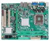
Biostar 945GC-M7TE Setup Manual - Page 17
JSPDIF_OUT1: Digital Audio out Connectors, JAUDIOF1: Front Panel Audio Header
 |
View all Biostar 945GC-M7TE manuals
Add to My Manuals
Save this manual to your list of manuals |
Page 17 highlights
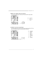
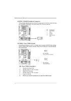
945GC-M7 TE JSPDIF_OUT1: Digital Audio out Connectors This connector allows user to connect the PCI bracket SPDIF output header. Pin Assignment 1 +5V 2 SPDIF_OUT1 3 Ground 3 1 JAUDIOF1: Front Panel Audio Header This header allows user to connect the front audio output cable with the PC front panel. It will disable the output on back panel audio connectors. 9 1 10 2 Pin Assignment 1 Mic Left in 2 Ground 3 Mic Right in 4 GPIO 5 Right line in 6 Jack Sense 7 Front Sense 8 Key 9 Left line in 10 Jack Sense 15
-
 1
1 -
2
-
3
-
4
-
5
-
6
-
7
-
8
-
9
-
10
-
11
-
 12
12 -
 13
13 -
 14
14 -
 15
15 -
 16
16 -
 17
17 -
 18
18 -
 19
19 -
 20
20 -
 21
21 -
 22
22 -
23
-
24
-
25
-
26
-
27
-
28
-
29
-
30
-
31
-
32
-
33
-
34
-
35
-
36
-
37
-
38
-
39
-
40
-
41
-
42
-
43
-
44
-
45
-
46
-
47
-
48
-
49
 |
 |

945GC-M7 TE
15
JSPDIF_OUT1: Digital Audio out Connectors
This connector allows user to connect the PCI bracket SPDIF output header.
Pin
Assignment
1
+5V
2
SPDIF_OUT1
1
3
3
Ground
JAUDIOF1: Front Panel Audio Header
This header allows user to connect the front audio output cable with the PC front
panel. It will disable the output on back panel audio connectors.
Pin
Assignment
1
Mic Left in
2
Ground
3
Mic Right in
4
GPIO
5
Right line in
6
Jack Sense
7
Front Sense
8
Key
9
Left line in
10
Jack Sense
1
9
2
10