Biostar I915G-M7 I915G-M7 user's manual - Page 16
JCMOS1: Clear CMOS Header, Clear CMOS Procedures, JATXPWR1/PATXPWR2: Power Connectors
 |
View all Biostar I915G-M7 manuals
Add to My Manuals
Save this manual to your list of manuals |
Page 16 highlights
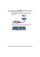
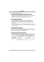
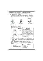
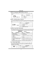
I915G-M7 JCMOS1: Clear CMOS Header By placing the jumper on pin2-3, it allows user to restore the BIOS safe setting and the CMOS data, please carefully follow the procedures to avoid damaging the motherboard. JCMOS1 Assignment Pin 1-2 close Normal Operation (Default). Pin 2-3 close Clear CMOS data. ※ Clear CMOS Procedures: 1. Remove AC power line. 2. Set the jumper to "Pin 2-3 close". 3. Wait for five seconds. 4. Set the jumper to "Pin 1-2 close". 5. Power on the AC. 6. Reset your desired password or clear the CMOS data. JATXPWR1/PATXPWR2: Power Connectors JATXPWR1: This connector allows user to connect with 20-pin power connector on the ATX power supply. JATXPWR2: By connecting this connector, it will provide +12V to CPU power circuit. Pin Assignment Pin Assignment 1 +3.3V 13 1 2 +3.3V 13 +3.3V 14 -12V 3 Ground 15 Ground 4 +5V 5 Ground 16 PS_ON 17 Ground 6 +5V 7 Ground 18 Ground 19 Ground 24 12 8 PW_OK 20 -5V 9 Standby Voltage +5V 21 +5V JATXPWR1 10 +12V 11 +12V 22 +5V 23 +5V 12 2 x 12 Detect 24 Ground 1 3 Pin Assignment Pin Assignment 1 +12V 2 JATXPWR2 2 +12v 3 Ground 4 Ground 14
-
 1
1 -
2
-
3
-
4
-
5
-
6
-
7
-
8
-
9
-
10
-
 11
11 -
 12
12 -
 13
13 -
 14
14 -
 15
15 -
 16
16 -
 17
17 -
 18
18 -
 19
19 -
 20
20 -
 21
21 -
22
-
23
-
24
-
25
-
26
-
27
-
28
 |
 |