Biostar I945G-M7 v1.x I945G-M7 user's manual
Biostar I945G-M7 v1.x Manual
 |
View all Biostar I945G-M7 v1.x manuals
Add to My Manuals
Save this manual to your list of manuals |
Biostar I945G-M7 v1.x manual content summary:
- Biostar I945G-M7 v1.x | I945G-M7 user's manual - Page 1
energy and, if not installed and used in accordance with the instructions, may cause harmful interference to radio communications. There is no guarantee vendor's approval in writing. The content of this user's manual is subject to be changed without notice and we will not be responsible for any mistakes - Biostar I945G-M7 v1.x | I945G-M7 user's manual - Page 2
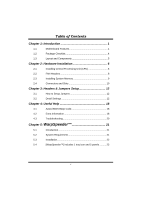
Jumpers 12 3.2 Detail Settings 12 Chapter 4: Useful Help 18 4.1 Award BIOS Beep Code 18 4.2 Extra Information 18 4.3 Troubleshooting 20 Chapter 5: WarpSpeeder 21 5.1 Introduction 21 5.2 System Requirement 21 5.3 Installation 22 5.4 [WarpSpeeder™] includes 1 tray icon and - Biostar I945G-M7 v1.x | I945G-M7 user's manual - Page 3
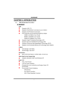
(Intel EM64T). Chipset North Bridge: Intel 945G. South Bridge: Intel ICH7. Dimensions Micro ATX Form Factor: 24.45cm (W) x 24.4cm (L) Operating System Supporting Supports Windows 2000, and Windows XP. Super I/O Chip: ITE IT8712F. Low Pin Count Interface. Provides the most commonly used legacy Super - Biostar I945G-M7 v1.x | I945G-M7 user's manual - Page 4
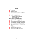
*1 DDR2_A2 DDR2_B1 128MB/256MB/512MB/1GB *1 128MB/256MB/512MB/1GB *1 Max is 4GB. DDR2_B2 128MB/256MB/512MB/1GB *1 On Board IDE One on-board connector supports 2 devices. Supports PIO Mode 0~4 Supports Ultra DMA 33/66/100 Bus Master Mode. On Board AC'97 Sound Codec Chip: REALTEK ALC655 - Biostar I945G-M7 v1.x | I945G-M7 user's manual - Page 5
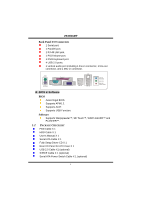
rate up to 3GB/s. Internal On-board I/O Connectors and Headers 1 IDE connector supports 2 hard disk devices. 1 front panel header supports front panel facilities. 1 CD-in connector supports 1 CD-ROM audio-in device. 1 front audio header supports front panel audio-out function. 1 S/PDIF-out connector - Biostar I945G-M7 v1.x | I945G-M7 user's manual - Page 6
Base/Center B. BIOS & Software BIOS Award legal BIOS. Supports APM1.2. Supports ACPI Supports USB Function. Software Supports Warpspeeder™, 9th Touch™, WINFLASHER™ and FLASHER™. 1.2 PACKAGE CHECKLIST FDD Cable X 1 HDD Cable X 1 User's Manual X 1 Serial ATA Cable X 1 Fully Setup Driver CD X 1 Rear - Biostar I945G-M7 v1.x | I945G-M7 user's manual - Page 7
I945G-M7 1.3 LAYOUT AND COMPONENTS JATXPWR2 JCFAN1 JKBMS1 LGA775 COMJC1OM1 CPU1 FDD1 JPRNT1 DDR2_A1 DDR2_A2 DDR2_B1 DDR2_B2 JVGA1 IDE1 JRJ45USB1 Super I/O Intel 945G JAUDIO1 JAUDIO2 JATXPWR1 PCI-EX16 JCDIN1 Codec PCI-EX1_1 PCI1 BIOS JDJ1 (optional) BAT1 LAN PCI2 JSPDIF_OUT1 - Biostar I945G-M7 v1.x | I945G-M7 user's manual - Page 8
COM1 I945G-M7 CHAPTER 2: HARDWARE INSTALLATION 2.1 INSTALLING CENTRAL PROCESSING UNIT (CPU) CPU1 Special Notice: Remove Pin Cap before installation, and make good preservation for future use. When the CPU is removed, cover the Pin Cap on the empty socket to ensure pin legs won't be damaged. Pin Cap - Biostar I945G-M7 v1.x | I945G-M7 user's manual - Page 9
I945G-M7 Step 2: Look for the black cut edge on socket, and the white dot on CPU should point forwards this black cut edge. The CPU will fit only in the correct orientation. Step 2-1: Step 2-2: Step 3: Hold the CPU down firmly, and then close the lever to complete the installation. Step 4: Put the - Biostar I945G-M7 v1.x | I945G-M7 user's manual - Page 10
System Fan Header COM1 Pin 1 2 3 JSFAN1 31 Assignment Ground +12V FAN RPM rate sense Note: The JCFAN1 and JSFAN1 support system cooling fan with Smart Fan Control utility. It supports 4-pin and 3-pin head connector. When connecting with wires onto connectors, please note that the red wire is the - Biostar I945G-M7 v1.x | I945G-M7 user's manual - Page 11
CO M1 DDR2_A1 DDR2_A2 DDR2_B1 DDR2_B2 I945G-M7 2.3 INSTALLING SYSTEM MEMORY 1. Unlock a DIMM slot by pressing the retaining clips outward. Align a DIMM on the slot such that the notch on the DIMM matches the break on the Slot. 2. Insert the DIMM vertically and firmly into the slot until the - Biostar I945G-M7 v1.x | I945G-M7 user's manual - Page 12
-M7 2.4 CONNECTORS AND SLOTS FDD1: Floppy Disk Connector The motherboard provides a standard floppy disk connector that supports 360K, 720K, 1.2M, 1.44M and 2.88M floppy disk types. This connector supports the provided floppy drive ribbon cables. 34 33 COM1 2 1 IDE1: Hard Disk Connector The - Biostar I945G-M7 v1.x | I945G-M7 user's manual - Page 13
8GB/s totally. PCI-EX1_1: PCI-Express x1 slot - PCI-Express 1.0a compliant. - Data transfer bandwidth up to 250MB/s per direction; 500MB/s in total. - PCI-Express supports a raw bit-rate of 2.5Gb/s on the data pins. - 2X bandwidth over the traditional PCI architecture. PCI-EX16 PCI-EX1_1 11 COM1 - Biostar I945G-M7 v1.x | I945G-M7 user's manual - Page 14
I945G-M7 CHAPTER 3: HEADERS & JUMPERS SETUP 3.1 HOW TO SETUP JUMPERS The illustration shows how to set up jumpers. When the jumper cap is placed on pins, the jumper is "close", if not, that means the jumper is "open". Pin opened Pin closed Pin1-2 closed 3.2 DETAIL SETTINGS JATXPWR1: ATX Power - Biostar I945G-M7 v1.x | I945G-M7 user's manual - Page 15
I945G-M7 JATXPWR2: ATX Power Connector By connecting this connector, it will provide +12V to CPU power circuit. COM1 2 1 4 3 Pin Assignment 1 +12V 2 +12V 3 Ground 4 Ground SATA1~SATA4: Serial ATA Connectors The motherboard has a PCI to SATA Controller with 4 channels SATA interface, - Biostar I945G-M7 v1.x | I945G-M7 user's manual - Page 16
COM1 +5V for PS/2 keyboard and mouse. 3 1 Pin 2-3 close PS/2 keyboard and mouse are powered by +5V standby voltage. Note: In order to support this function "Power-on system via keyboard and mouse", "JKBV1" jumper cap should be placed on Pin 2-3. JAUDIO2: Front Panel Audio Header This header - Biostar I945G-M7 v1.x | I945G-M7 user's manual - Page 17
I945G-M7 JPANEL1: Front Panel Header This 24-pin connector includes Power-on, Reset, HDD LED, Power LED, Sleep button, speaker and IrDA Connection. It allows user to connect the PC case's front panel switch functions. COM1 PWR_LED SLP On/Off ++ 2 1 +- SPK RST HLED IR 24 23 IR Pin - Biostar I945G-M7 v1.x | I945G-M7 user's manual - Page 18
I945G-M7 JCDIN1: CD-ROM Audio-in Connector This connector allows user to connect the audio source from the variety devices, like CD-ROM, DVD-ROM, PCI sound card, PCI TV turner card etc.. COM1 1 4 Pin Assignment 1 Left channel input l 2 Ground 3 Ground 4 Right channel input JCMOS1: Clear - Biostar I945G-M7 v1.x | I945G-M7 user's manual - Page 19
I945G-M7 JSPDIF_OUT1: Digital Audio-out Connector This connector allows user to connect the PCI bracket SPDIF output header. COM1 Pin Assignment 1 +5V 2 SPDIF_OUT 3 Ground 3 1 JSPDIF_IN1 (optional): Digital Audio-in Connector This connector allows user to connect the PCI bracket SPDIF - Biostar I945G-M7 v1.x | I945G-M7 user's manual - Page 20
I945G-M7 CHAPTER 4: USEFUL HELP 4.1 AWARD BIOS BEEP CODE Beep Sound One long beep followed by two short beeps High-low siren sound One Short beep when system boot-up Long beeps every other second Meaning Video card not found or video card memory bad CPU overheated System will shut down - Biostar I945G-M7 v1.x | I945G-M7 user's manual - Page 21
I945G-M7 B. CPU Overheated If the system shutdown automatically after power on system for seconds, that means the CPU protection function has been activated. When the CPU is over heated, the motherboard will shutdown automatically to avoid a damage of the CPU, and the system may not power on again. - Biostar I945G-M7 v1.x | I945G-M7 user's manual - Page 22
I945G-M7 4.3 TROUBLESHOOTING Probable Solution 1. No power to the system at all 1. Make sure power cable is Power light don't illuminate, fan securely plugged in. inside power supply does not turn 2. Replace cable. on. 3. Contact technical support. 2. Indicator light on keyboard does not - Biostar I945G-M7 v1.x | I945G-M7 user's manual - Page 23
automatically rebooting the computer and then restart to a speed that is either the original system speed or a suitable one. 5.2 SYSTEM REQUIREMENT OS Support: Windows 98 SE, Windows Me, Windows 2000, Windows XP DirectX: DirectX 8.1 or above. (The Windows XP operating system includes DirectX 8.1. If - Biostar I945G-M7 v1.x | I945G-M7 user's manual - Page 24
be automatically and immediately launched after you click "Finish" button. Usage: The following figures are just only for reference, the screen printed in this user manual will change according to your motherboard on hand. 22 - Biostar I945G-M7 v1.x | I945G-M7 user's manual - Page 25
I945G-M7 5.4 [WARPSPEEDER™] INCLUDES 1 TRAY ICON AND 5 PANELS 1. Tray Icon: Whenever the Tray Icon utility is launched, it will display a little tray icon on the right side of Windows Taskbar. This utility is responsible for conveniently invoking [WarpSpeeder™] Utility. You can use the mouse by - Biostar I945G-M7 v1.x | I945G-M7 user's manual - Page 26
I945G-M7 2. Main Panel If you click the tray icon, [WarpSpeeder™] utility will be invoked. Please refer to the following figure; the utility's first window you will see is Main Panel. Main Panel contains features as follows: a. Display the CPU Speed, CPU external clock, Memory clock, AGP clock, and - Biostar I945G-M7 v1.x | I945G-M7 user's manual - Page 27
I945G-M7 3. Voltage Panel Click the Voltage button in Main Panel, the button will be highlighted and the Voltage Panel will slide out to up as the following figure. In this panel, you can decide to increase CPU core voltage and Memory voltage or not. The default setting is "No". If you want to get - Biostar I945G-M7 v1.x | I945G-M7 user's manual - Page 28
3MHz button", "-1MHz button", "+1MHz button", and "+3MHz button": provide user the ability to do real-time overclock adjustment. Warning: Manually overclock is potentially dangerous, especially when the overclocking percentage is over 110 %. We strongly recommend you verify every speed you overclock - Biostar I945G-M7 v1.x | I945G-M7 user's manual - Page 29
I945G-M7 c. "Auto-overclock button": User can click this button and [WarpSpeeder™] will set the best and stable performance and frequency automatically. [WarpSpeeder™] utility will execute a series of testing until system fail. Then system will do fail-safe reboot by using Watchdog function. After - Biostar I945G-M7 v1.x | I945G-M7 user's manual - Page 30
I945G-M7 6. About Panel Click the "about" button in Main Panel, the button will be highlighted and the About Panel will slide out to up as the following figure. In this panel, you can get model name and detail information in hints of all the chipset that are related to overclocking. You can also get - Biostar I945G-M7 v1.x | I945G-M7 user's manual - Page 31
I945G-M7 Note: Because the overclock, overvoltage, and hardware monitor features are controlled by several separate chipset, [WarpSpeeder™] divide these features to separate panels. If one chipset is not on board, the correlative button in Main panel will be disabled, but will not interfere other
-
 1
1 -
 2
2 -
 3
3 -
 4
4 -
 5
5 -
 6
6 -
 7
7 -
8
-
9
-
10
-
11
-
12
-
13
-
14
-
15
-
16
-
17
-
18
-
19
-
20
-
21
-
22
-
23
-
24
-
25
-
26
-
27
-
28
-
29
-
30
-
31
 |
 |

I945G-M7
i
FCC Information and Copyright
This equipment has been tested and found to comply with the limits of a Class
B digital device, pursuant to Part 15 of the FCC Rules. These limits are designed
to provide reasonable protection against harmful interference in a residential
installation. This equipment generates, uses and can radiate radio frequency
energy and, if not installed and used in accordance with the instructions, may
cause harmful interference to radio communications. There is no guarantee
that interference will not occur in a particular installation.
The vendor makes no representations or warranties with respect to the
contents here and specially disclaims any implied warranties of merchantability
or fitness for any purpose. Further the vendor reserves the right to revise this
publication and to make changes to the contents here without obligation to
notify any party beforehand.
Duplication of this publication, in part or in whole, is not allowed without first
obtaining the vendor’s approval in writing.
The content of this user’s manual is subject to be changed without notice and
we will not be responsible for any mistakes found in this user’s manual. All the
brand and product names are trademarks of their respective companies.