Biostar I945G-M7 v1.x I945G-M7 user's manual - Page 19
JSPDIF_OUT1: Digital Audio-out Connector, JSPDIF_IN1 optional: Digital Audio-in Connector, JDJ1:
 |
View all Biostar I945G-M7 v1.x manuals
Add to My Manuals
Save this manual to your list of manuals |
Page 19 highlights
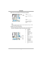
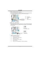
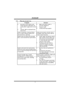
I945G-M7 JSPDIF_OUT1: Digital Audio-out Connector This connector allows user to connect the PCI bracket SPDIF output header. COM1 Pin Assignment 1 +5V 2 SPDIF_OUT 3 Ground 3 1 JSPDIF_IN1 (optional): Digital Audio-in Connector This connector allows user to connect the PCI bracket SPDIF input header. COM1 Pin Assignment 1 +5V 2 SPDIF_IN 3 Ground 3 1 JDJ1: AUDIO DJ Connector (optional) COM1 135 Pin Assignment 1 SMBDATA 2 SMBCLK 3 INT_B 4 Key 5 AXT_PWROK 17
-
 1
1 -
2
-
3
-
4
-
5
-
6
-
7
-
8
-
9
-
10
-
11
-
12
-
13
-
 14
14 -
 15
15 -
 16
16 -
 17
17 -
 18
18 -
 19
19 -
 20
20 -
 21
21 -
 22
22 -
 23
23 -
 24
24 -
25
-
26
-
27
-
28
-
29
-
30
-
31
 |
 |

I945G-M7
17
JSPDIF_OUT1: Digital Audio-out Connector
This connector allows user to connect the PCI bracket SPDIF output header.
Pin
Assignment
1
+5V
2
SPDIF_OUT
C
O
M
1
1
3
3
Ground
JSPDIF_IN1 (optional): Digital Audio-in Connector
This connector allows user to connect the PCI bracket SPDIF input header.
Pin
Assignment
1
+5V
2
SPDIF_IN
C
O
M
1
1
3
3
Ground
JDJ1: AUDIO DJ Connector (optional)
Pin
Assignment
1
SMBDATA
2
SMBCLK
3
INT_B
4
Key
1
C
O
M
1
3
5
5
AXT_PWROK