Biostar M6VCF M6VCF user's manual - Page 22
Front USB Connector USB2
 |
View all Biostar M6VCF manuals
Add to My Manuals
Save this manual to your list of manuals |
Page 22 highlights
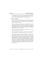
Chapter 1 Front USB Connector (USB2) Motherboard Description Pin Signal Name Pin Signal Name 1 +5V 2 Ground 3 USBP2- 4 Ground 5 USBP2+ 6 USBP3+ 7 Ground 8 USBP3- 9 Ground 10 +5V NOTES: After version 1.0, the ATX POWER (POWER1) will be removed just beside the KB/MS (CN1) & USB (USB1) port. ( in vertical position)
-
 1
1 -
2
-
3
-
4
-
5
-
6
-
7
-
8
-
9
-
10
-
11
-
12
-
13
-
14
-
15
-
16
-
 17
17 -
 18
18 -
 19
19 -
 20
20 -
 21
21 -
 22
22 -
 23
23 -
 24
24 -
 25
25 -
 26
26 -
 27
27 -
28
-
29
-
30
-
31
-
32
-
33
-
34
-
35
-
36
-
37
-
38
-
39
-
40
-
41
-
42
-
43
-
44
-
45
-
46
-
47
-
48
-
49
-
50
-
51
-
52
-
53
-
54
-
55
-
56
-
57
-
58
-
59
-
60
-
61
-
62
-
63
-
64
-
65
-
66
-
67
-
68
-
69
-
70
-
71
-
72
-
73
-
74
-
75
-
76
-
77
-
78
-
79
-
80
-
81
-
82
 |
 |

Chapter 1
Motherboard Description
Ã5Ã:
Front USB Connector (USB2)
Pin
Signal Name
Pin
Signal Name
1
+5V
2
Ground
3
USBP2-
4
Ground
5
USBP2+
6
USBP3+
7
Ground
8
USBP3-
9
Ground
10
+5V
NOTES: After version 1.0, the ATX POWER (POWER1) will be
removed just beside the KB/MS (CN1) & USB (USB1) port. ( in vertical
position)
±²³´
±