Biostar M7NCD M7NCD user's manual
Biostar M7NCD Manual
 |
View all Biostar M7NCD manuals
Add to My Manuals
Save this manual to your list of manuals |
Biostar M7NCD manual content summary:
- Biostar M7NCD | M7NCD user's manual - Page 1
energy and, if not installed and used in accordance with the instructions, may cause harmful interference to radio communications. There is no guarantee the vendor's approval in writing. The content of this user's manual is subject to be changed without notice and we will not be responsible for any - Biostar M7NCD | M7NCD user's manual - Page 2
: DIMMB1, DIMMB2 6 Jumpers, Headers, Connectors & Slots 7 DEUTSCH 14 Spezifikationen von M7NCD 14 Verpackungsinhalt 15 Einstellung der Jumper 16 Installation der CPU 16 DDR-DIMM-Modules: DIMMB1 ...39 System Requirement 39 Installation...40 Usage...41 TROUBLE SHOOTING 49 PROBLEMLÖSUNG 50 ii - Biostar M7NCD | M7NCD user's manual - Page 3
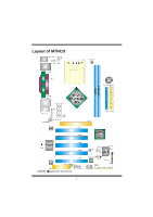
Layout of M7NCD ※NOTE: ●represents the first pin. 1 - Biostar M7NCD | M7NCD user's manual - Page 4
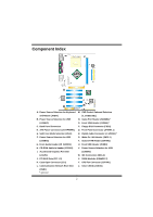
(JPANEL1) E. Safe/ User Mode Selection (JCLK) R. Digital Audio Connector (J_SPDIF1) * F. Power Source Selection for USB S. Wake On LAN Header (JWOL1) (JUSBV2) T. System FAN Header (JSFAN1) G. Front Audio Header (JF_AUDIO1) U. Front USB Header (JUSB3) H. CD-ROM Audio-In Header (JCDIN1 - Biostar M7NCD | M7NCD user's manual - Page 5
English M7NCD Features A. Hardware CPU Provides Socket-462. Supports the AMD® processor up to XP 3200+. Front Side Bus at 266/333/400 MHz. Chipset North Bridge: nVIDIA nFORCE2 400. South Bridge: nVIDIA nFORCE2 MCP/ MCP-T. Main Memory Supports up to 2 DDR devices. Supports 266/333/400MHz (without ECC - Biostar M7NCD | M7NCD user's manual - Page 6
) and WatchdogTM. Offers the highest performance for Windows 98 SE, Windows 2000, Windows Me, Windows XP, SCO UNIX etc. Package contents HDD Cable X1 FDD Cable X1 User's Manual X1 USB Cable X1 (optional) Rear I/O Panel for ATX Case X1 (optional) Fully Setup Driver CD X1 StudioFun! Application CD X1 - Biostar M7NCD | M7NCD user's manual - Page 7
How to setup Jumper The illustration shows how jumpers are setup. When the Jumper cap is placed on pins, the jumper is "close". If no jumper cap is placed on the pins, the jumper is "open". The illustration shows a 3-pin jumper whose pin 1and 2 are "close" when jumper cap is placed on these 2 pins. - Biostar M7NCD | M7NCD user's manual - Page 8
Unbuffered DIMMs DIMM Socket Location DIMMB1 DIMMB2 DDR Module 64MB/128MB/256MB/512MB/1GB *1 64MB/128MB/256MB/512MB/1GB *1 ***Only for reference*** Total Memory Size (MB) Max is 2GB Installing DDR Module 1. Unlock a DIMM slot by pressing the retaining clips outward. Align a DIMM on the slot such - Biostar M7NCD | M7NCD user's manual - Page 9
supports the provided floppy drive ribbon cables. Hard Disk Connectors: IDE1/ IDE2 The motherboard has a 32-bit Enhanced PCI IDE Controller that provides PIO Mode 0~4, Bus Master, and Ultra a hardware scalable riser card interface, which supports audio, network and modem only. Power Connectors: - Biostar M7NCD | M7NCD user's manual - Page 10
(-) 14 Power Button 16 Ground 18 KEY 20 KEY 22 Ground 24 IRRX Function Sleep Button NA POWER LED Power-on Button IrDA Connector Front USB Header: JUSB3 Pin Assignment Pin 2 10 1 +5V(fused) 2 1 9 3 USBP4- 4 5 USBP4+ 6 JUSB3 7 Ground 8 9 KEY 10 Wake On - Biostar M7NCD | M7NCD user's manual - Page 11
voltage of 5V JUSBV2: JUSBLAN1 port powered with standby voltage of 5V JUSBV3: JUSB3 port powered with standby voltage of 5V Note: In order to support this function "Power-on the system via USB device", "JUSBV1/JUSBV2/ JUSBV3" jumper cap should be placed on pin 2-3 respectively. 9 - Biostar M7NCD | M7NCD user's manual - Page 12
Data The following procedures are for resetting the BIOS password. It is important to follow these instructions closely. ※ Clear CMOS Procedures: 1. Remove 1 JC1 2 Assignment Case Open Signal Ground CD-ROM Audio-In Header: JCDIN1 1 4 JCDIN1 Pin Assignment 1 Left Channel Input 2 Ground - Biostar M7NCD | M7NCD user's manual - Page 13
Assignment 1 Mic In/ Center 2 Ground 3 Mic Power/ Bass 4 Audio Power 5 Right Line Out/ Speaker 6 Right Line Out/ Speaker Out mode User Mode (default) Pin 1-2 Open (133/ 166/ 200 MHz) Note: When overclock function failed and system is unable to boot-up, please follow the instruction - Biostar M7NCD | M7NCD user's manual - Page 14
Digital Audio Connector: J_SPDIF1 (optional) 3 1 Pin Assignment 1 +5V 2 SPDIF_OUT 3 Ground Game Header: JGAME1 (optional) 15 1 16 2 Pin Assignment Pin Assignment 1 +5V 2 +5V 3 Joystick B Button 1 4 Joystick A Button 1 5 Joystick B - Biostar M7NCD | M7NCD user's manual - Page 15
1 CNR Codec is used 3 Pin 2-3 Close Back Panel Connectors J1394_USB1 PS/2 1394 Mouse (optional) JPRNT1 Parallel Port JUSBLAN1 LAN (optional) Line In Speaker Out MIC In PS/2 USB Keyboard JKBMS1 COM1 JCOM1 COM2 JCOM2 USB JAUDIO 13 - Biostar M7NCD | M7NCD user's manual - Page 16
von M7NCD A. Hardware CPU Unterstützung für Sockel 462. Unterstützung für den AMD® Prozessor bis zu XP 3200+. 1394-Ports mit der Datenübertragungsrate bis auf maximal 400Mbps. LAN (optional) Chip: RTL8201BL. Dopplete Geschwindigkeit von 10/100 Mbps und Ultra DMA 33/66/100/133 Bus Master Modus. 14 - Biostar M7NCD | M7NCD user's manual - Page 17
front audio header. 1 IEEE 1394A (FireWire) Anschluss. (optional) Abmessungen ATX Form-Factor: 19.9cm X 30.4cm (W X L) B. BIOS & Software BIOS Award legal BIOS. Windows 98SE, Windows 2000, Windows ME, Windows XP and SCO UNIX usw. . Verpackungsinhalt HDD Kable X1 FDD Kable X1 Benutzer Handbuch X1 USB - Biostar M7NCD | M7NCD user's manual - Page 18
Treiber CD für Installation X 1 StudioFun! Anwendung CD X 1 (optional) Einstellung der Jumper Die Abbildung verdeutlicht, wie Jumper eingestellt werden. Pins werden durch die Jumper-Kappe verdeckt, ist der Jumper "geschlossen". Keine Pins werden durch die Jumper-Kappe verdeckt, ist der Jumper "geö - Biostar M7NCD | M7NCD user's manual - Page 19
CPU-Lüfter Header: JCFAN1 3 1 JCFAN1 Pin Beschreibung 1 Masse 2 +12V 3 Lüfter RPM Geschwindigkeit Sensor System-Lüfter Header: JSFAN1 Pin Beschreibung 1 JSFAN1 1 Masse 2 +12V 3 Lüfter RPM Geschwindigkeit Sensor e DDR-DIMM-Modules: DIMMB1, DIMMB2 DRAM-Zugriffszeit: 2.5V Unbuffered - Biostar M7NCD | M7NCD user's manual - Page 20
-Controller, der die Modi PIO0~4, Bus Master sowie die Ultra DMA/33/66/100/133- Funktion zur Verfügung stellt direkt an die Grafikkarte angeschlossen. Dieses Motherboard unterstützt Grafikkarten für PCI-Slots, aber , welche nur Audio, Netzwerk und Modem unterstützt. Digital Audio Anschluss: J_SPDIF1 - Biostar M7NCD | M7NCD user's manual - Page 21
Stromversorgungsanschluss: JATXPWER1 10 20 PIN Belegung PIN 1 +3.3V 11 2 +3.3V 12 3 Masse 13 4 +5V 14 5 Masse 15 1 11 6 +5V 16 7 Masse 17 JATXPWER1 8 PW_OK 18 9 +5V reservierte 19 Spannung 10 +12V 20 Anschlüsse für die Vorderseite: JPANEL1 Belegung +3.3V -12V - Biostar M7NCD | M7NCD user's manual - Page 22
: JUSB3 Pin Belegung Pin Belegung 2 10 1 +5V(geschmelzt) 2 +5V(geschmelzt)) 1 9 3 USB- 4 USB- JUSB3 5 USB+ 6 7 Masse 8 USB+ Masse 9 Kein Pin 10 Kein Wake On LAN Header: JWOL1 Pin 3 1 1 2 JWOL1 3 Belegung +5V_SB Masse Aufwecken Auswahl von Stromsmodi für Tastatur - Biostar M7NCD | M7NCD user's manual - Page 23
Spannung für JUSB3 zum Erwecken Anmerkung: Um die Funktion ─"Erwecken durch USB-Geräte"─zu aktivieren, müssen Pins 2-3 von JUSBV1/JUSBV2/JUSBV3 CMOS-Daten Löschen Die folgende Schritte leiten Sie, das Kennwort für BIOS-System zurückzusetzen. Es ist wichtig, die Anweisung zu folgen. 21 - Biostar M7NCD | M7NCD user's manual - Page 24
14 JF_AUDIO1 Pin Belegung Pin Belegung 1 Mikrofon-Eingang/ 2 Zentrum Masse 3 Mikrofon-Betriebsspannung/ 4 Bass Audio-Betriebsspannung 5 Audio-Signal des rechten 6 Audio-Signal des rechten Kanals zur Vorderseite / Kanals zur Vorderseite / Lautsprecher-Signal des Lautsprecher-Signal - Biostar M7NCD | M7NCD user's manual - Page 25
-Signal des linken 14 Audio-Signal des linken Kanals von der Vorderseite/ Kanals von der Vorderseite/ Lautsprecher-Signal des Lautsprecher-Signal des linken Kanals von der linken Kanals von der Vorderseite Vorderseite Safe/ User Modi Auswahl: JCLK JCLK 1 Pin 1-2 geschlossen 1 Beschreibung - Biostar M7NCD | M7NCD user's manual - Page 26
Game Header: JGAME1 (optional) 15 1 16 2 Pin Belegung Pin 1 +5V 2 3 Joystick B Knopf 1 4 5 Joystick B Koordierung X 6 7 MIDI Ausgabe 8 9 Joystick B Koordierung Y 10 11 Joystick B Knopf 2 12 13 MIDI Eingabe 14 15 Kein 16 Belegung +5V Joystick A Knopf 1 Joystick A - Biostar M7NCD | M7NCD user's manual - Page 27
Anschlüsse für die Rückwand J1394_USB1 PS/2 1394 Maus (optional) JPRNT1 Parallel Port JUSBLAN1 LAN (optional) Line In Speaker Out MIC In PS/2 USB Tastatur JKBMS1 COM1 JCOM1 COM2 JCOM2 USB JAUDIO 25 - Biostar M7NCD | M7NCD user's manual - Page 28
to know that when overclocking, the system can be at a vulnerable state. Therefore, the BIOSTAR Watchdog Technology was designed BIOS setting. Under this circumstance, please power off your PC. After that, press and power on your system simultaneously to restart your system. This user - Biostar M7NCD | M7NCD user's manual - Page 29
Furthermore, Users can take snapshots of video and customize the saved images as screensavers or photo slideshows. Of course, the images can be stored in USB mass storage devices like flash disks and USB floppy disks. Hardware Requirements The supported hardware list of StudioFun! updates regularly - Biostar M7NCD | M7NCD user's manual - Page 30
. If Windows or GNU/Linux is the only OS installed on the hard disk with no free space, it be prompted to choose the DVD area/region selection code. Choose this based on the type of DVDs you the type of mouse installed. The distribution currently supports PS/2, USB and Serial mice. In case of serial - Biostar M7NCD | M7NCD user's manual - Page 31
StudioFun! Recover Where there is a MBR (Master Boot record) corruption, the "StudioFun Recover" will automatically probe the hard disk master boot record and find out the installed operating system(s). Once success, it will re-install the boot loader with correct options in the MBR. Please be noted - Biostar M7NCD | M7NCD user's manual - Page 32
it is put in to the drive when the Desktop (StudioFun! shell) is up and running whereas the control will simply glow to inform the user about a VCD present in the DVD/CD-ROM drive when the Desktop is not launched. 2. DVD This control will glow whenever a DVD is detected in - Biostar M7NCD | M7NCD user's manual - Page 33
it is put in to the drive when the Desktop (StudioFun! shell) is up and running, otherwise, the control will simply glow to inform the user about a AUDIO present in the DVD/CD-ROM drive. 5. FILE This control will glow whenever a File CD (CDs with other media type files) is detected in - Biostar M7NCD | M7NCD user's manual - Page 34
it is not glowing, except the eject media and exit, the media-player will just come up and wait for user input. Software Details XINE XINE is a multimedia player. It plays back Audio CD, DVD, and VCD. It also decodes multimedia files like AVI, MOV, WMV, and MP3 from local disk drives - Biostar M7NCD | M7NCD user's manual - Page 35
e. DVD/VCD menus (requires external plug-in) f. Audio and subtitle channel selection g. Closed Caption support h. Brightness, contrast, audio volume, hue, saturation adjusting requires hardware/driver support) i. Playlist j. Image snapshot k. Audio re-sampling l. Software de-interlacing algorithms - Biostar M7NCD | M7NCD user's manual - Page 36
Control Support. a. Infrared interface b. User-friendly • Usage of StudioFun! with CelomaChrome skin a. Select VCD button to play a VCD disc b. Select DVD button to play a DVD disc c. Select CDDA button to play a Audio CD d. Select next chapter or MRL (>>|) button to play next track in Audio CD - Biostar M7NCD | M7NCD user's manual - Page 37
Select Region Overview Select region is a utility to set a DVD region. With the help of this application user can set or change a DVD region. Only one region can be set at a time. About Select Region With the help of this application you can - Biostar M7NCD | M7NCD user's manual - Page 38
chosen at random. The demo is terminated as soon as there is any mouse or keyboard activity. The xscreensaver-demo program is the graphical user interface to xscreensaver. It lets you tune the various parameters used by the xscreensaver daemon, and browse through the graphics demos. StudioFun! comes - Biostar M7NCD | M7NCD user's manual - Page 39
program to change the current resolution settings of the Display. By default user of StudioFun! will be given a choice to select between any of is a utility to copy files from deferent devices to hard disk and vice versa. User can copy files from devices such as, floppy, CD-Rom and Flashdisk to hard - Biostar M7NCD | M7NCD user's manual - Page 40
About File manager The hard disk files are stored in a directory called "/studiofun" on the hard disk. You can also delete files from hard disk, but you cannot delete files from any device. Select device - Contains the device names /floppy, /cdrom and /flashdisk. Select a device from/to which you - Biostar M7NCD | M7NCD user's manual - Page 41
that is either the original system speed or a suitable one. System Requirement OS Support: Windows 98 SE, Windows Me, Windows 2000, Windows XP DirectX: DirectX 8.1 or above. (The Windows XP operating system includes DirectX 8.1. If you use Windows XP, you do not need to install DirectX 8.1.) 39 - Biostar M7NCD | M7NCD user's manual - Page 42
Installation 1. Execute the setup execution file, and then the following dialog will pop up. Please click "Next" button and follow the default procedure to install. 2. When you see the following dialog in setup procedure, it means setup is completed. If the "Launch the WarpSpeeder Tray Utility" - Biostar M7NCD | M7NCD user's manual - Page 43
Usage The following figures are just only for reference, the screen printed in this user manual will change according to your motherboard on hand. [WarpSpeeder™] includes 1 tray icon and 5 panels: 1. Tray Icon: Whenever the Tray Icon utility is launched, it will display a little tray icon on the - Biostar M7NCD | M7NCD user's manual - Page 44
do the following figure; the utility's first window you will see is Main Panel. Main Panel contains features as follows: a. Display the CPU Speed, CPU external clock, Memory clock, AGP clock, and PCI clock information. b. Contains About, Voltage, Overclock, and Hardware Monitor Buttons for invoking - Biostar M7NCD | M7NCD user's manual - Page 45
and the Voltage Panel will slide out to up as the following figure. In this panel, you can decide to increase CPU core voltage and Memory voltage or not. The default setting is "No". If you want to get the best performance of overclocking, we recommend you click the option "Yes". 43 - Biostar M7NCD | M7NCD user's manual - Page 46
4. Overclock Panel Click the Overclock button in Main Panel, the button will be highlighted and the Overclock Panel will slide out to left as the following figure. 44 - Biostar M7NCD | M7NCD user's manual - Page 47
: a. "-3MHz button", "-1MHz button", "+1MHz button", and "+3MHz button": provide user the ability to do real-time overclock adjustment. Warning: Manually overclock is potentially dangerous, especially when the overclocking percentage is over 110 %. We strongly recommend you verify every speed you - Biostar M7NCD | M7NCD user's manual - Page 48
c. "Auto-overclock button": User can click this button and [ WarpSpeeder™ ] will set the best and stable to the Recovery Dialog's setting. Note: Because the testing programs, invoked in Auto-overclock and Verify, include DirectDraw, Direct3D and DirectShow tests, the DirectX 8.1 or newer runtime - Biostar M7NCD | M7NCD user's manual - Page 49
as the following figure. In this panel, you can get model name and detail information in hints of all the chipset that are related to overclocking. You can also get the mainboard's BIOS model and the Version number of [ WarpSpeeder™ ] utility. 47 - Biostar M7NCD | M7NCD user's manual - Page 50
Note: Because the overclock, overvoltage, and hardware monitor features are controlled by several separate chipset, [ WarpSpeeder™ ] divide these features to separate panels. If one chipset is not on board, - Biostar M7NCD | M7NCD user's manual - Page 51
Trouble Shooting PROBABLE SOLUTION No power to the system at all Power light don't * Make sure power cable is securely plugged in illuminate, fan inside power supply does not turn on. Indicator light on keyboard does not turn on * Replace cable * Contact technical support or * Review system's - Biostar M7NCD | M7NCD user's manual - Page 52
Problemlösung MÖGLICHE URSACHE LÖSUNG Das System hat keine Spannungsversorgung. * Versichern Sie sich, dass das Stromkabel richtig Die Stromanzeige leuchtet nicht, der Lüfter im angebracht ist Inneren der eingeschaltet. Stromversorgung Tastaturleuchten sind wird nicht nicht an. * Ersetzen - Biostar M7NCD | M7NCD user's manual - Page 53
07/22/2003 51
-
 1
1 -
 2
2 -
 3
3 -
 4
4 -
 5
5 -
 6
6 -
 7
7 -
8
-
9
-
10
-
11
-
12
-
13
-
14
-
15
-
16
-
17
-
18
-
19
-
20
-
21
-
22
-
23
-
24
-
25
-
26
-
27
-
28
-
29
-
30
-
31
-
32
-
33
-
34
-
35
-
36
-
37
-
38
-
39
-
40
-
41
-
42
-
43
-
44
-
45
-
46
-
47
-
48
-
49
-
50
-
51
-
52
-
53
 |
 |

M
M
7
7
N
N
C
C
D
D
i
FCC Information and Copyright
This equipment has been tested and found to comply with the limits of a
Class B digital device, pursuant to Part 15 of the FCC Rules. These limits
are designed to provide reasonable protection against harmful
interference in a residential installation. This equipment generates, uses
and can radiate radio frequency energy and, if not installed and used in
accordance with the instructions, may cause harmful interference to radio
communications. There is no guarantee that interference will not occur in
a particular installation.
The vendor makes no representations or warranties with respect to the
contents here of and specially disclaims any implied
warranties
of
merchantability or fitness for any purpose. Further the vendor reserves
the right to revise this publication and to make changes to the contents
here of without obligation to notify any party beforehand.
Duplication of this publication, in part or in whole, is not allowed without
first obtaining the vendor’s approval in writing.
The content of this user’s manual is subject to be changed without notice
and we will not be responsible for any mistakes found in this user’s
manual. All the brand and product names are trademarks of their
respective companies.