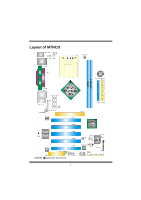
Biostar M7NCD M7NCD user's manual - Page 8
DDR DIMM Modules: DIMMB1, DIMMB2 - memory
 |
View all Biostar M7NCD manuals
Add to My Manuals
Save this manual to your list of manuals |
Page 8 highlights
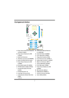
CPU Fan Header: JCFAN1 3 1 JCFAN1 Pin No. 1 2 3 System Fan Header: JSFAN1 Pin No. 1 1 2 JSFAN1 3 Assignment Ground +12V FAN rpm Rate Sense Assignment Ground +12V FAN rpm Rate Sense DDR DIMM Modules: DIMMB1, DIMMB2 DRAM Access Time: 2.5V Unbuffered DDR 266/333/400 MHz Type required. DRAM Type: 64MB/ 128MB/ 256MB/ 512MB/ 1GB DIMM Module (184 pin) Total Memory Size with Unbuffered DIMMs DIMM Socket Location DIMMB1 DIMMB2 DDR Module 64MB/128MB/256MB/512MB/1GB *1 64MB/128MB/256MB/512MB/1GB *1 ***Only for reference*** Total Memory Size (MB) Max is 2GB Installing DDR Module 1. Unlock a DIMM slot by pressing the retaining clips outward. Align a DIMM on the slot such that the notch on the DIMM matches the break on the slot. 2. Insert the DIMM firmly and vertically into the slot until the retaining chip snap back in place and the Dimm is properly seated. 6
-
 1
1 -
2
-
 3
3 -
 4
4 -
 5
5 -
 6
6 -
 7
7 -
 8
8 -
 9
9 -
 10
10 -
 11
11 -
 12
12 -
 13
13 -
14
-
15
-
16
-
17
-
18
-
19
-
20
-
21
-
22
-
23
-
24
-
25
-
26
-
27
-
28
-
29
-
30
-
31
-
32
-
33
-
34
-
35
-
36
-
37
-
38
-
39
-
40
-
41
-
42
-
43
-
44
-
45
-
46
-
47
-
48
-
49
-
50
-
51
-
52
-
53
 |
 |
