Biostar M7SUA M7SUA user's manual - Page 9
Audio Modem Riser Slot: AMR1, Front Panel Connector: JPANEL1, Front USB Header: JUSB2 - support
 |
View all Biostar M7SUA manuals
Add to My Manuals
Save this manual to your list of manuals |
Page 9 highlights
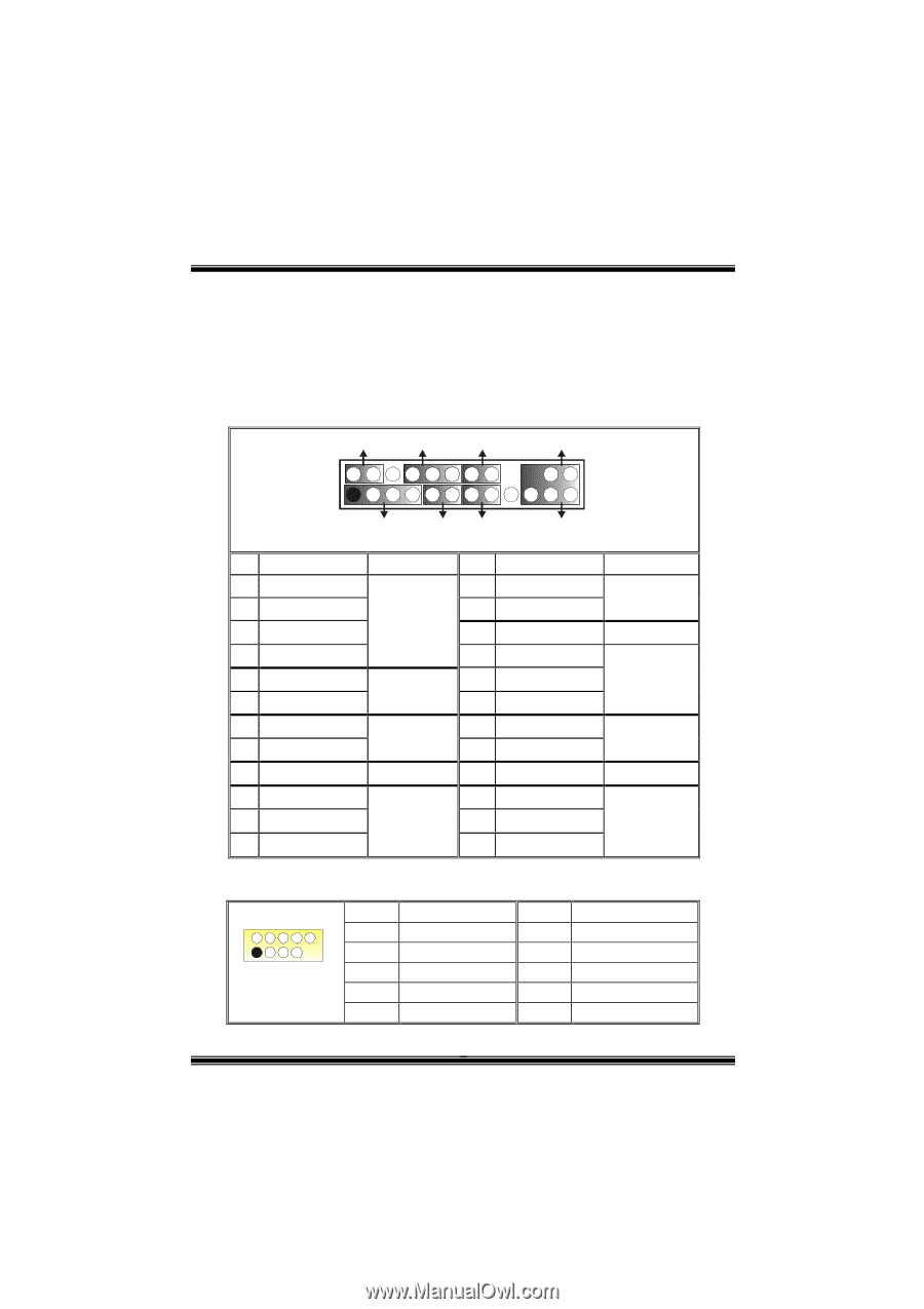
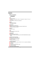
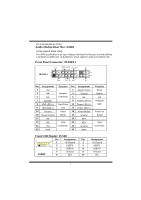
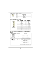
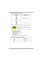
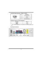
slot is designated as 32 bits. Audio Modem Riser Slot: AMR1 (Only support slave card) The AMR specification is an open Industry Standard Architecture and that defines a hardware scalable riser card interface, which supports audio and modem only. Front Panel Connector: JPANEL1 SLP PWR_LED ON/OFF (+) (+) (-) 2 JPANEL1 1 (+) (-) SPK HLED RST IR 24 23 IR Pin Assignment 1 +5V 3 NA 5 NA 7 Speaker 9 HDD LED (+) 11 HDD LED (-) 13 Ground 15 Reset Control 17 NA 19 NA 21 +5V 23 IRTX Function Speaker Connector Hard Drive LED Reset Button IrDA Connector Pin Assignment 2 Sleep Control 4 Ground 6 NA 8 Power LED (+) 10 Power LED (+) 12 Power LED (-) 14 Power Button 16 Ground 18 KEY 20 KEY 22 Ground 24 IRRX Function Sleep Button NA POWER LED Power-on Button IrDA Connector Front USB Header: JUSB2 Pin Assignment Pin 2 10 1 +5V(fused) 2 1 9 3 USBP3- 4 5 USBP3+ 6 JUSB2 7 Ground 8 9 KEY 10 Assignment +5V(fused) USBP2USBP2+ Ground NA 7
-
 1
1 -
2
-
3
-
 4
4 -
 5
5 -
 6
6 -
 7
7 -
 8
8 -
 9
9 -
 10
10 -
 11
11 -
 12
12 -
 13
13 -
 14
14 -
15
-
16
-
17
-
18
-
19
-
20
-
21
-
22
-
23
-
24
-
25
-
26
-
27
-
28
-
29
-
30
-
31
-
32
-
33
-
34
-
35
-
36
 |
 |