Biostar M7VIK M7VIK user's manual
Biostar M7VIK Manual
 |
View all Biostar M7VIK manuals
Add to My Manuals
Save this manual to your list of manuals |
Biostar M7VIK manual content summary:
- Biostar M7VIK | M7VIK user's manual - Page 1
radio frequency energy and, if not installed and used in accordance with the instructions, may cause harmful interference to radio communications. There is no guarantee that for any mistakes found in this user's manual. All the brand and product names are trademarks of their respective companies. i - Biostar M7VIK | M7VIK user's manual - Page 2
11 Contenido del Paquete...12 Disposición del M7VIK ...12 Instalación de la CPU ...13 Módulos DDR DIMM: DIMM1-2-3 14 Puentes, Cabezales, Conectores y Ranuras 16 WARPSPEEDER 21 Introduction...21 System Requirement...22 Installation...22 Usage...24 TROUBLE SHOOTING 32 SOLUCIÓN DE PROBLEMAS 33 ii - Biostar M7VIK | M7VIK user's manual - Page 3
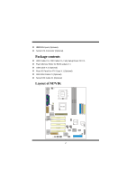
USB2.0 High Speed Device. The KT400 system controller is designed to support 200/266/333/400 MHz DDR SDRAM DIMMs. Supports one CNR Slot (Type B only), one AGP 8X Slot, and five 32-bit PCI Bus slots. Complies with PC ATX form factor specifications. Supports popular operating systems such as Windows - Biostar M7VIK | M7VIK user's manual - Page 4
Cable X 1, FDD Cable X 1, Fully Setup Driver CD X 1 Flash Memory Writer for BIOS update X 1 USB Cable X 2 (Optional) Rear I/O Panel for ATX Case X 1 (Optional) IEEE1394 Cable X1 (Optional) Serial ATA Cable X1 (Optional) Layout of M7VIK 11 JKBV1 JUSBV1 JCOM1 CPU1 Socket A Mic-In Line-In Sp-Out - Biostar M7VIK | M7VIK user's manual - Page 5
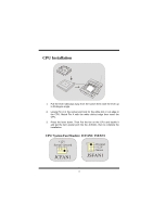
up to 90-degree angle. 2. Locate Pin A in the socket and lock for the white dot or cut edge in the CPU. Match Pin A with the white dot/cut edge then insert the CPU. 3. Press the lever down. Then Put the fan on the CPU and buckle it and put the fan's power port - Biostar M7VIK | M7VIK user's manual - Page 6
Module (184 pin) Only support 4 bank for DDR PC3200 (2pcs Double-Side or 3 pcs Single-Side). DIMM Socket Location DDR Module Total Memory Size (MB) DIMM 1 reference. If use FSB333MHz CPU, the Memory support only DDR333 (PC2700). List of the status of DDR 400 already passed Clock Vender Serial - Biostar M7VIK | M7VIK user's manual - Page 7
can only fit into the slot in one direction. 2. Push the tabs out. Insert the DIMM memory modules into the socket at a 90-degree angle, then push down vertically so that it will fit into the place. 3. The Mounting Holes and plastic tabs should fit over - Biostar M7VIK | M7VIK user's manual - Page 8
motherboard supports video cards for PCI slots, but it is also equipped with an Accelerated Graphics Port (AGP). An AGP card will take advantage of AGP technology for improved video efficiency and performance, especially with 3D graphics. Communication Network Riser Slot: CNR1 The CNR specification - Biostar M7VIK | M7VIK user's manual - Page 9
Peripheral Component Interconnect Slots: PCI1-5 This motherboard is equipped with 5 standard PCI slots. PCI stands for Peripheral Component Interconnect, and it is a bus standard for expansion cards, which has, supplanted the older - Biostar M7VIK | M7VIK user's manual - Page 10
Pin10 ==> NA Front Panel Connector: JPANEL1 PWR_LED SLP (+) (+) (-) ON/OFF IR 2 24 1 23 (+) (-) SPK RST IR HLED SPK ==> Speaker Conn. HLED ==> Hard Driver LED RST ==> Reset Button IR ==> Infrared Conn. SLP ==> Sleep Button PWR_LED ==> Power LED ON/ OFF ==> Power-on Button 8 - Biostar M7VIK | M7VIK user's manual - Page 11
CPU Clock Selection: JCLK1 63 41 JCLK1 Pin 1-2, 5-6 ==> 100 Mhz Pin 2-3, 5-6 ==> 133 Mhz (default) Pin 2-3, 4-5 ==> 166Mhz Audio Subsystem: JAUDIO1/ JCDIN1 2 1 1 JAUDIO1 JCDIN1 (Front Audio Header) (CD- - Biostar M7VIK | M7VIK user's manual - Page 12
Back Panel Connectors JKBMS1 PS/2 Mouse JUSB1 JPRNT1 Parallel JGAME1 Game Port PS/2 Keyboard USB COM1 JCOM1 COM2 JCOM2 Speaker Line In Mic Out In 10 - Biostar M7VIK | M7VIK user's manual - Page 13
M7VIK Usa Chipsets VIA KT400 / VT8235, Winbond W83697HF. Contiene facilidades I/O integrados en la placa madre en el que incluye dos puertos en serie, un puerto paralelo, un puertos de ratón PS/2, un puerto de teclado PS/2, puertos de audio, puertos USB y un puerto de juego. Soporta Single Socket - Biostar M7VIK | M7VIK user's manual - Page 14
ón completa del Driver CD X 1 Flash Memory Writer para actualización del BIOS X 1 Cable USB X 2 (Opcional) Panel Trasero I/O para Caja ATX X 1 (Opcional) Cable IEEE1394 X1 (Opcional) Cable Serial ATA X1 (Opcional) Disposición del M7VIK 11 JKBV1 JUSBV1 JCOM1 CPU1 Socket A Entrada Entrad - Biostar M7VIK | M7VIK user's manual - Page 15
y busque el punto blanco o corte el borde en la CPU. Empareje el contacto A con el punto blanco/ corte del borde, luego inserte la CPU. 3. Presione la palanca para abajo. Ponga el ventilador en la CPU y abróchelo. Luego ponga el puerto de corriente del ventilador en el JCFAN1. Y ya habrá completado - Biostar M7VIK | M7VIK user's manual - Page 16
/128MB/256MB/512MB/1GB *1 DIMM 2 64MB/128MB/256MB/512MB/1GB *1 Máximo de 3GB DIMM3 64MB/128MB/256MB/512MB/1GB *1 La lista de arriba para la configuración DRAM es solamente para referencia. Si utiliza FSB333MHz CPU, la memoria soporta solamente DDR333 (PC2700). Listado del estado del DDR400 - Biostar M7VIK | M7VIK user's manual - Page 17
El zócalo DIMM tiene una lengüeta plástica de seguridad y el módulo de memoria DIMM tiene una muesca asimétrica, así el módulo de memoria DIMM puede caber solamente en la ranura de una sóla dirección. 2. Tire la lengüeta hacia afuera. Inserte los módulos de memoria DIMM en el zócalo a los 90 grados - Biostar M7VIK | M7VIK user's manual - Page 18
controlador SATA con 2 canales de interface SATA, que satisface el spec de SATA 1.0 y también puede transferir datos de hasta una velocidad de 1.5GHz soporta corriente AGP de 1.5V) Su monitor se fijará directamente a la tarjeta de video. Ésta placa madre soporta tarjetas de video para ranuras PCI, - Biostar M7VIK | M7VIK user's manual - Page 19
ón en el que suplanta a la antigua bus estándar ISA, en su mayoría de las partes. Ésta ranura PCI está diseñado con 32 bits. Conector de Corriente: JATXPWR1 JATXPWR1 (Conector de Corriente ATX) Cabezal Wake On LAN: WOL1 Tierra Wake up 5V_SB WOL1 Cabezal Frontal USB: JUSB2/3 2 1 JUSB2/3 Contacto1 - Biostar M7VIK | M7VIK user's manual - Page 20
del Panel Frontal: JPANEL1 PWR_LED SLP (+) (+) (-) ON/OFF IR 2 24 1 23 (+) (-) SPK RST IR HLED SPK HLED RST IR ==> Conector de Altavoz ==> LED del Disco Duro ==> Boton de Reinicio ==> Conector Infrarojo SLP ==> Boton de Suspension PWR_LED ==> Corriente LED ON/ OFF ==> Boton - Biostar M7VIK | M7VIK user's manual - Page 21
ón del Reloj del CPU: JCLK1 63 41 JCLK1 Contacto 1-2, 5-6 ==> 100 Mhz Contacto 2-3, 5-6 ==> 133 Mhz (default) Contacto 2-3, 4-5 ==> 166Mhz Subsistema de Audio: JAUDIO1/ JCDIN1 2 1 JAUDIO1 (Cabezal Frontal de Audio) 1 JCDIN1 (Cabezal de Entrada de Audio CD-ROM) Puente de Borrar CMOS: JCMOS1 - Biostar M7VIK | M7VIK user's manual - Page 22
Conectores del Panel Trasero JKBMS1 Raton PS/2 JUSB1 JPRNT1 Paralelo JGAME1 Puerto de Juego Teclado USB PS/2 COM1 JCOM1 COM2 JCOM2 Salida del Entrada Entrada Altavoz de Linea del MIC 20 - Biostar M7VIK | M7VIK user's manual - Page 23
well as the chipset information. Also, in the About panel, you can get detail descriptions about BIOS model and chipsets. In addition, the frequency status of CPU, memory, AGP and PCI along with the CPU speed are synchronically shown on our main panel. Moreover, to protect users' computer systems if - Biostar M7VIK | M7VIK user's manual - Page 24
System Requirement OS Support: Windows 98 SE, Windows Me, Windows 2000, Windows XP DirectX: DirectX 8.1 or above. (The Windows XP operating system includes DirectX 8.1. If you use Windows XP, - Biostar M7VIK | M7VIK user's manual - Page 25
2. When you see the following dialog in setup procedure, it means setup is completed. If the "Launch the WarpSpeeder Tray Utility" checkbox is checked, the Tray Icon utility and [ WarpSpeeder™ ] utility will be automatically and immediately launched after you click "Finish" button. 23 - Biostar M7VIK | M7VIK user's manual - Page 26
Usage The following figures are just only for reference, the screen printed in this user manual will change according to your motherboard on hand. [ WarpSpeeder™ ] includes 1 tray icon and 5 panels: 1. Tray Icon: Whenever the Tray Icon utility is launched, it will display a little tray icon on the - Biostar M7VIK | M7VIK user's manual - Page 27
you will see is Main Panel. Main Panel contains features as follows: a. Display the CPU Speed, CPU external clock, Memory clock, AGP clock, and PCI clock information. b. Contains About, Voltage, Overclock, and Hardware Monitor Buttons for invoking respective panels. c. With a user-friendly Status - Biostar M7VIK | M7VIK user's manual - Page 28
highlighted and the Voltage Panel will slide out to up as the following figure. In this panel, you can decide to increase CPU core voltage and Memory voltage or not. The default setting is "No". If you want to get the best performance of overclocking, we recommend you click the option "Yes". 26 - Biostar M7VIK | M7VIK user's manual - Page 29
3MHz button": provide user the ability to do real-time overclock adjustment. Warning: Manually overclock is potentially dangerous, especially when the overclocking percentage is over 110 %. We strongly recommend you verify every speed you overclock by click the Verify button. Or, you can just click - Biostar M7VIK | M7VIK user's manual - Page 30
or load the verified best and stable frequency according to the Recovery Dialog's setting. Note: Because the testing programs, invoked in Auto-overclock and Verify, include DirectDraw, Direct3D and DirectShow tests, the DirectX 8.1 or newer runtime library is required. And please make sure your - Biostar M7VIK | M7VIK user's manual - Page 31
as the following figure. In this panel, you can get model name and detail information in hints of all the chipset that are related to overclocking. You can also get the mainboard's BIOS model and the Version number of [ WarpSpeeder™ ] utility. 29 - Biostar M7VIK | M7VIK user's manual - Page 32
30 - Biostar M7VIK | M7VIK user's manual - Page 33
Note: Because the overclock, overvoltage, and hardware monitor features are controlled by several separate chipset, [ WarpSpeeder™ ] divide these features to separate panels. If one chipset is not on board, - Biostar M7VIK | M7VIK user's manual - Page 34
Trouble Shooting PROBABLE SOLUTION No power to the system at all Power light don't * Make sure power cable is securely plugged in illuminate, fan inside on. Indicator light on power supply does not keyboard does not turn turn on * Replace cable * Contact technical support * Review system's - Biostar M7VIK | M7VIK user's manual - Page 35
ayuda técnica. CAUSA PROBABLE SOLUCIÓN Sistema inoperativo. Luz del teclado encendido, * Presione los dos extremos del DIMM, presione luz de indicador de corriente iluminado, disco para abajo firmemente hasta que el módulo rígido está girando. encaje en el lugar. CAUSA PROBABLE SOLUCI - Biostar M7VIK | M7VIK user's manual - Page 36
09/5/2002 34
-
 1
1 -
 2
2 -
 3
3 -
 4
4 -
 5
5 -
 6
6 -
 7
7 -
8
-
9
-
10
-
11
-
12
-
13
-
14
-
15
-
16
-
17
-
18
-
19
-
20
-
21
-
22
-
23
-
24
-
25
-
26
-
27
-
28
-
29
-
30
-
31
-
32
-
33
-
34
-
35
-
36
 |
 |

M
M
M
7
7
7
V
V
V
I
I
I
K
K
K
i
FCC Statement and Copyright
This equipment has been tested and found to comply with the limits of a
Class B digital device, pursuant to Part 15 of the FCC Rules. These limits
are designed to provide reasonable protection against harmful interference
in a residential installation. This equipment generates, uses and can
radiate radio frequency energy and, if not installed and used in
accordance with the instructions, may cause harmful interference to radio
communications. There is no guarantee that interference will not occur in a
particular installation.
The vendor makes no representations or warranties with respect to the
contents here of and specially disclaims any implied warranties of
merchantability or fitness for any purpose. Further the vendor reserves the
right to revise this publication and to make changes to the contents here of
without obligation to notify any party beforehand.
Duplication of this publication, in part or in whole is not allowed without
first obtaining the vendor’s approval in writing.
The content of this user’s is subject to be changed without notice and we
will not be responsible for any mistakes found in this user’s manual. All the
brand and product names are trademarks of their respective companies.