Biostar M7VIP M7VIP BIOS setup guide - Page 19
UR2 Duplex Mode
 |
View all Biostar M7VIP manuals
Add to My Manuals
Save this manual to your list of manuals |
Page 19 highlights
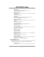
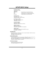
M7VIP BIOS Setup Onboard FDC Controller Select Enabled if your system has a floppy disk controller (FDC) installed on the system board and you wish to use it. If install and FDC or the system has no floppy drive, select Disabled in this field. The Choices: Enabled (default), Disabled. Onboard Serial Port 1 Select an address and corresponding interrupt for the first and second serial ports. The Choices: Disabled, 3F8/IRQ4 (default), 2F8/IRQ3, 3E8/IRQ4, 2E8/IRQ3, Auto. Onboard Serial Port 2 Select an address and corresponding interrupt for the first and second serial ports. The Choices: Disabled, 2F8/IRQ3 (default), 3F8/IRQ4, 3E8/IRQ4, 2E8/IRQ3, Auto. UART Mode Select This item allows you to determine which Infra Red (IR) function of onboard I/O chip. The Choices: Normal (default), AS KIR, IrDA. RxD, TxD Active This item allows you to determine which Infrared (IR) function of onboard I/O chip. The Choices: Hi / Lo (default), Hi / Hi, Lo / Hi, Lo / Lo. IR Transmission Delay This item allows you to enable/disable IR transmission delay. The Choices: Enabled (default), Disabled. UR2 Duplex Mode Select the value required by the IR device connected to the IR port. Full-duplex mode permits simultaneous two-direction transmission. Half-duplex mode permits transmission in one direction only at a time. The Choices: Half (default), Full. Use IR Pins Consult your IR peripheral documentation to select the correct setting of the TxD and RxD signals. The Choices: IR-Rx2Tx2 (default), RxD2, TxD2. Onboard Parallel Port This item allows you to determine access onboard parallel port controller with which I/O Address. The Choices: 378/IRQ7 (default), 278/IRQ5, 3BC/IRQ7, Disabled. 18
-
 1
1 -
2
-
3
-
4
-
5
-
6
-
7
-
8
-
9
-
10
-
11
-
12
-
13
-
 14
14 -
 15
15 -
 16
16 -
 17
17 -
 18
18 -
 19
19 -
 20
20 -
 21
21 -
 22
22 -
 23
23 -
 24
24 -
25
-
26
-
27
-
28
-
29
-
30
 |
 |